2 connecting rs-232c, Caution, Connecting trigger input – KEYENCE N-400 User Manual
Page 21: Pin assignment, Rs-232c cable connections
Chapter 2 Installation Procedure
13
2
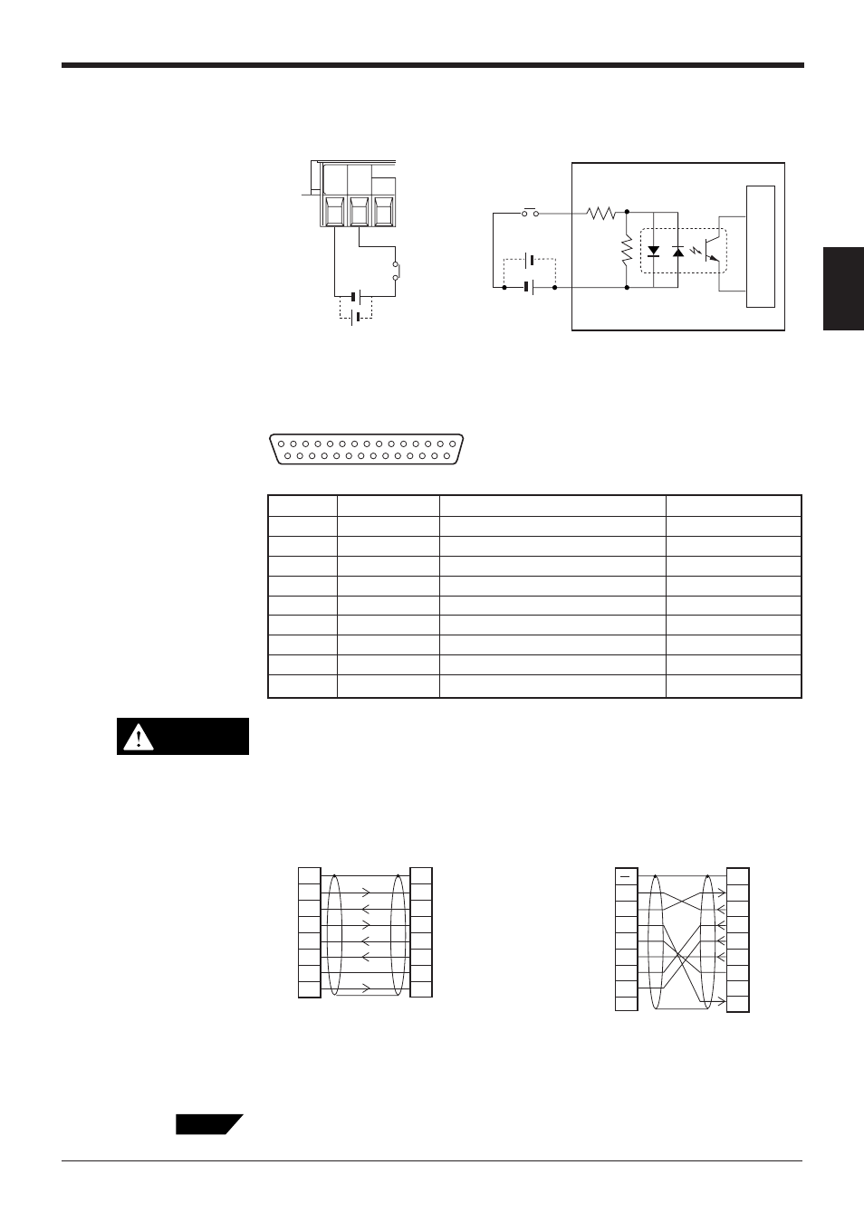
Connecting trigger input
To use multi-head scan mode, connect the trigger input to the N-400 only, instead
of to each BL series unit.
2.2.2 Connecting RS-232C
Pin assignment
Pin No. 25 is used for a 5 V power supply output. Do not connect this termi-
nal to the ground terminal or any other terminal when it is unused. Doing this
may damage the N-400 or the external device connected to this terminal.
RS-232C cable connections
■
Connecting personal computer
• Connecting the computer with 25-pin
• Connecting IBM PC
A commercially-available straight cable (D-sub 25 pin - 25 pin, or D-sub 25 pin - 9
pin) can be used.
CAUTION
2
Computer
SD
RD
RS
CS
DR
SG
ER
3
4
5
6
2
1
1
N-400
SD
FG
FG
RD
SG
RS
CS
DR
ER
3
4
5
6
7
20
7
20
D-sub 25-pin (male)
M2.6 screw
D-sub 25-pin (male)
M2.6 screw
2
PC
SD
CD
RD
RS
CS
DR
SG
ER
3
4
5
6
2
1
N-400
SD
FG
RD
SG
RS
CS
DR
ER
3
4
5
6
7
8
7
8
20
1
D-sub 25-pin (male)
M2.6 screw
Connector case
D-sub 9-pin (female)
#4-40 screw
Tips
TIM
SG
COM
15 to 26 VDC
+
+
Contact
or solid state
TIM
COM
Internal circuit
+
+
13
1
25
14
Pin No.
Symbol
Function
Signal direction
1
FG
Frame ground
—
2
SD (TXD)
Sends data.
Input
3
RD (RXD)
Receives data.
Output
4
RS (RTS)
Ready to send data.
Input
5
CS (CTS)
Request to send data.
Output
6
DR (DSR)
Connected to pin No. 20 inside.
Output
7
SG
Signal ground
—
20
ER (DTR)
Connected to pin No. 6 inside.
Input
25
+5 V
5 V power supply output (100 mA)
Output
* The OP-98769 cable (1.5 m: manu
factured by KEYENCE) and the
OP25057 conversion connector can
be used.
* The OP-98769 cable (1.5 m: manufactured
by KEYENCE) can be used.
D-sub 25-pin (male)
DCE specification (defined as terminal)
M2.6 screw