3 part names, N-400 – KEYENCE N-400 User Manual
Page 13
Chapter 1 Overview of The N-400
1
SD
RD
SD
TERMINATOR
RD
CS
RS
TEST
RS-232C
RS-455
POWER TIMING
N-400
ON
OFF
ON
OFF
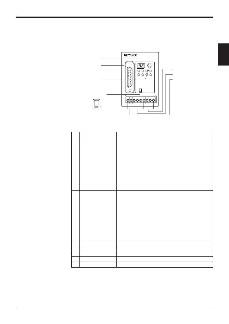
1
Display LEDs
6
Power supply terminal
7
RS-485 terminal
8
Trigger input terminal
2
RS-232C port
3
Communication
status indicator LEDs
4
Test switch
5
Terminator switch
No. Name
Function
1
Display LEDs
• Normally displays “00” (ID number of the N400).
• Displays the ID number of the device being tested.
(
➮
See p. 26.)
• Displays “S1 (51)” to indicate setup mode.
(
➮
See p. 75.)
• Displays “S0 (50)” to indicate initial communication status
after a setting change.
(
➮
See p. 48.)
• Displays the N-400’s error condition.
(
➮
See 131.)
• Displays the ID number of the device currently connected
when sending a hotline command.
(
➮
See p. 73.)
2
RS-232C port
• Connect a host computer or PLC to this connector.
3
• POWER: Lit when power is ON.
• TIMING: Lit when the trigger input connected to the N-400
is ON.
(For the RS-232C connections)
Lit when the SD, RD, RS and CS signals are ON.
(For the RS-485 connections)
SD: Lit when the N-400 is sending data.
RD: Lit when the N-400 is receiving data.
* Both the SD and RD indicators are lit when the N-400 is
receiving data.
4
Test switch
Starts the connection test mode.
5
Terminator switch
Switches the terminator’s ON/OFF status.
6
Power supply terminal Connect a 24 VDC power supply.
7
RS-485 terminal
Used for the multi-drop link connection.
8
Trigger input terminal
Used for trigger input in multi-head scan mode.
1.3
Part Names
N-400
Communication
status indicator LEDs
5