KEYENCE N-400 User Manual
Page 117
109
Chapter 6 PLC Link
6
■
Data memory areas for each ID number
Bar code data read by the BL series for each ID number is stored in the areas of
“+00” to “+30” (based on the specified data memory head address). In the following
table, “A” indicates the data memory head address.
When ten BL series are connected, ten data memory areas exist (if the different
data memory head addresses are specified for each ID number).
Note: These data areas accept up to 255 digits. However, the BL series can read
only 32 digits. Therefore, all the areas for 255 digits are not used for the N-400.
Only the areas corresponding to the number of the data digits are used.
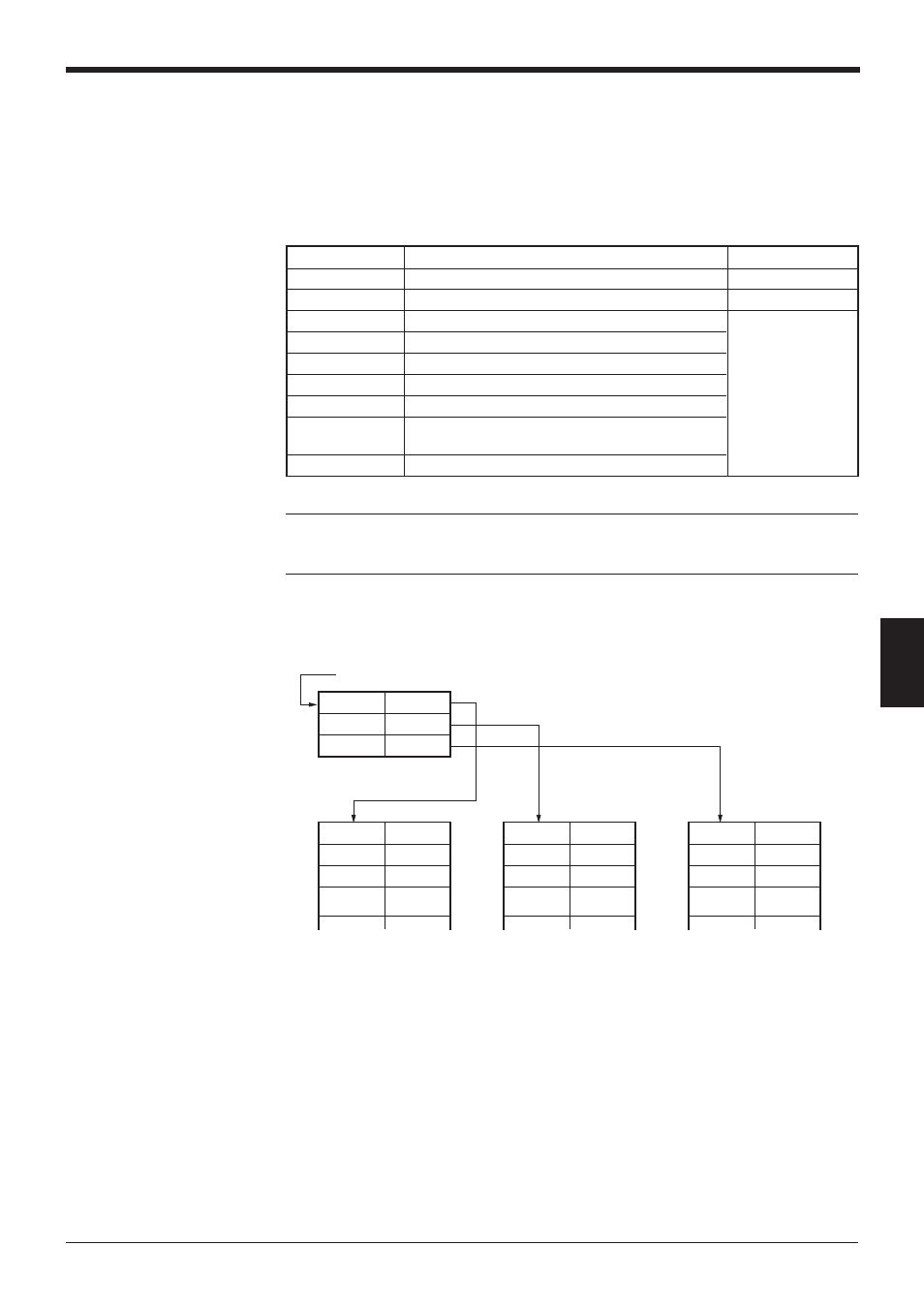
Example: When the head address is “100” and three BL series (ID nos. 1 to 3) are
connected:
Address
Description
Reference page
A + 00
Data memory flag area
pp. 110 and 111
A + 01
Reserved area
—
A + 02
ID number
A + 03
Number of digits of bar code data
A + 04
1st digit of bar code data
A + 05
2nd digit of bar code data
p. 112
A + 06
3rd digit of bar code data
:
:
:
:
A + 258
255th digit of bar code data
DM100
200
DM101
300
DM102
400
DM200
Flag
DM201
Reserved
DM202
ID
DM203
•
•
•
•
•
•
DM300
Flag
DM301
Reserved
DM302
ID
DM303
•
•
•
•
•
•
DM400
Flag
DM401
Reserved
DM402
ID
DM403
•
•
•
•
•
•
(ID1)
(ID2)
(ID3)
Head address: 100
Number of
digits
Number of
digits
Number of
digits