Final installation, Final checks, Precautions – Panasonic CQ VAD9300U User Manual
Page 77: Transportation bracket removal
Attention! The text in this document has been recognized automatically. To view the original document, you can use the "Original mode".
□ Final Installation
Lead Connections
Connect all wires, making sure that each connection is
insulated and secure. Bundle all loose wires and fasten
them with tape so they will not fall down later. Now insert
the LCD monitor into the mounting collar.
Congratulations! After making a few final checks, you’re
ready to enjoy your new LCD monitor.
□ Final Checks
1. Make sure that all wires are properly connected and
insulated.
2. Make sure that the LCD monitor is securely held in
the mounting collar.
3. Turn on the ignition to check the unit for proper
operation.
If you have difficulties, consult your nearest authorized pro
fessional installer for assistance.
□ Precautions
Cautions:
• We strongly recommend that you wear gloves for
installation work to protect yourself from injuries.
• When bending the mounting tab of the mounting col
lar with a screwdriver, be careful not to injure your
hands and fingers.
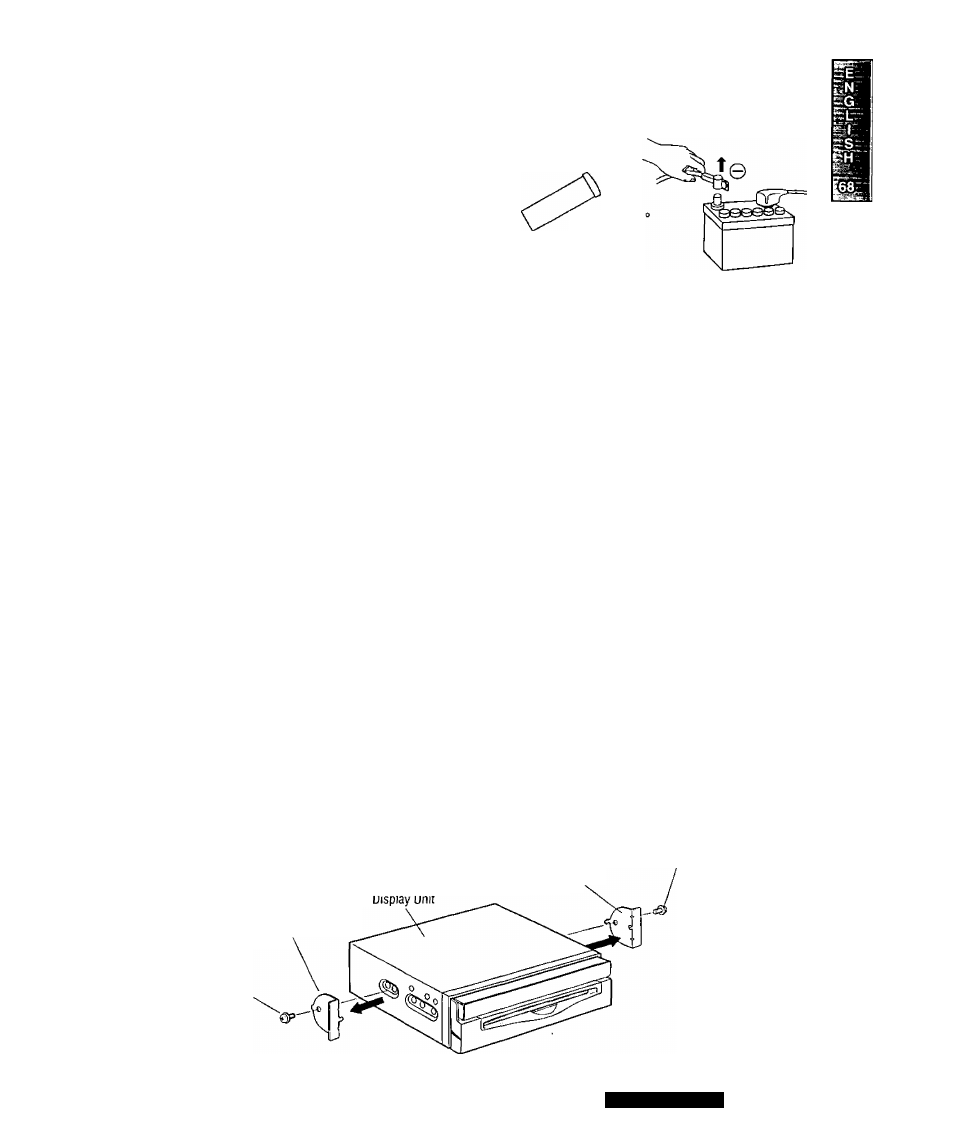
' Disconnect the cable from the negative (-) battery termi
nal (see caution at right).
' Unit should be installed in a horizontal position with the
front end up at a convenient angle, but less than 30°.
yess than 30
Caution; Do not disconnect the battery terminals ot a
car with trip or navigational computer since all user set
tings stored in memory will be lost. Instead take extra
care with installing the unit to prevent shorts.
This unit should be professionally installed. In case of diffi
culty, please consult with your nearest professional
installer.
1. This unit only operates in a 12-volt DC negative ground
system.
2. Follow the electrical connections carefully (=> page 84-
93). Failure to do so may result in damage to the unit.
3. Connect the power lead after all other connections are
made.
4. Be sure to connect the battery lead (yellow) to the posi
tive terminal (+) of the battery or fuse block (BAT) termi
nal.
5. Insulate all exposed wires to prevent short circuiting.
6. Secure all loose wires after installing the unit.
7. Please carefully read the operating and installation
instructions of the respective equipment before connect
ing it to this unit.
Caution; Please follow the laws and regulations of
your state, province or country for installation of the
unit.
□ Transportation Bracket Removal
Be sure to remove the transportation brackets before use (installation).
Use Binding-Head Screws (M5 x 6 mm) for installation. (e> page 78)
Be careful not to lose these Binding-Head Screws.
Transportation
Bracket
Transportation
Bracket
Binding-Head
Screws
(M5
X
6 mm)
Binding-Head
Screws
(M5 x6 mm)
CQ-VAD9300U
77