1 front panel layout and identification, 0 guitar input, 0 signal and peak meters – Yamaha FX770 User Manual
Page 7: 0 input level control, Output presence control, Output level control, Program number led display, 0 main lcd display, Effect select buttons, Mode select keys
Attention! The text in this document has been recognized automatically. To view the original document, you can use the "Original mode".
Section 1: FX770 Features and Controls
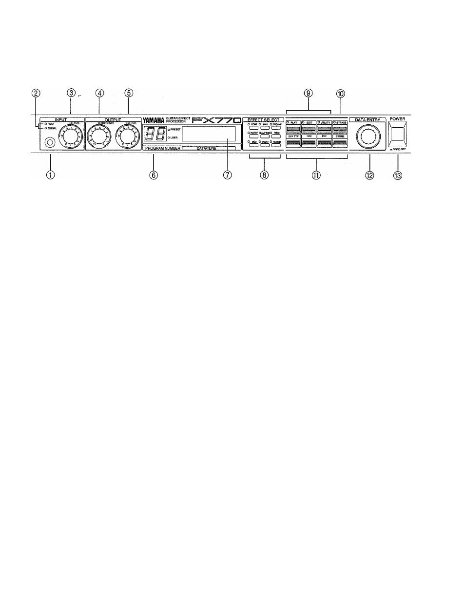
1.1 FRONT PANEL lAYOUT AND IDENTIFICATION
0
Guitar Input
Plug your guitar in here, and set the Input level according
to the instructions of the Input Level Control.
0 Signal and Peak Meters
These indicators provide a useful guide for setting input
levels and avoiding unwanted distortion. These LEDs
function for both Guitar Input and for the Insert Loop
Return according to how the Meter Select Switch is set
on the Rear Panel.
0 Input Level Control
For the optimum input level setting, play your guitar at the
highest output level it will be played in actual use, and
adjust the Input Level control so that the Signal LED
lights most of the time. The Peak LED should not flash
regularly (it may flash Occasionally in response to high-
level peaks).
© Output Presence Control
This control is a high-frequency roll-off that is located on
the main stereo outputs. You might generally set it around
“10”, and if you need the sound to be not so bright - turn
the control down.
© Output Level Control
This is the Master Output volume. On stage, or in the
studio, this will control how much output you get from the
FX770.
® Program Number LED display
This multi-functional displays show the currently se
lected Preset or User Program Number, or in the Tuner
Mode, it will display the Note name.
0
Main LCD Display
This is the main FX770 “information center”, providing
all of the information necessary for effect program selec
tion, programming and utility control.
® Effect Select Buttons
In Play mode, these buttons are used to turn Effects
Blocks on and off (See Section 3 THE PLAY MODE). In
Edit mode, they are used to select Effects Blocks for
editing (See Section 4 THE EDIT MODE).
Used to Select the corresponding Effect Block, these
buttons can also be used to bring an effect in or out of the
signal path.
® Mode Select Keys
These keys are used to select the Play, Edit, Utility, and
Bypass modes.
® Bypass Key
In play mode, this key is used to select the Bypass and
Tuner functions. In Edit mode, it is used to turn effects
blocks on and off while editing.
® Function Keys
In Edit mode, these keys are used to select effect types,
move the cursor, and store programs.
® DATA Wheel
Used for entering new values and selections, the DATA
Wheel makes programming fast and easy.
® AC Power Switch
In is On, out is Off. Any other setting of this button means
there is a problem.