2 load cells, 3 serial communications, Load cells – Rice Lake 720i Programmable Indicator/Controller - Installation Manual User Manual
Page 13: Serial communications
Installation
7
•
For load cell cables, cut the shield wire just
past the grounding clamp. Shield wire function
is provided by contact between the cable shield
and the grounding clamp.
•
Route stripped cables through cord grips and
clamps. Ensure shields contact grounding
clamps as shown in Figure 2-1. Tighten
grounding clamp nuts.
•
Finish installation using cable ties to secure
cables inside of indicator enclosure.
2.3.2
Load Cells
To attach cable from a load cell or junction box to the
720i
, route the cable through the cord grip and ground
the shield wire as described in Section 2.3.1 on page 6.
Next, remove load cell connector J1 from CPU board.
Wire the load cell cable from the load cell or junction
box to the connector as shown in Table 2-1.
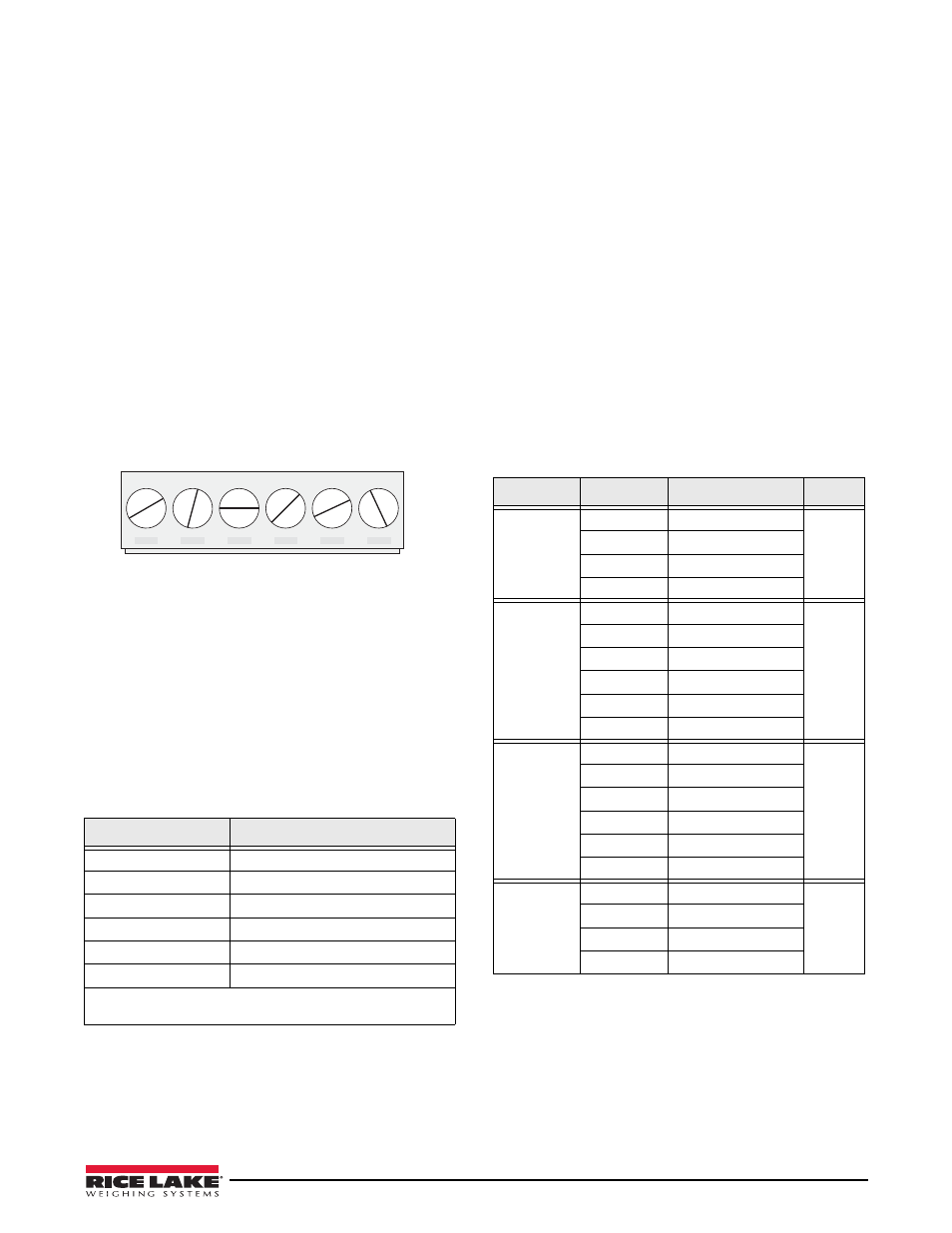
J1
LOAD CELL CONNECTOR
+SIG
–SIG
+SENS
–SENS
+EXC
–EXC
Figure 2-2. Load Cell Connector
If using 6-wire load cell cable (with sense wires),
remove jumpers JP1 and JP2 before reinstalling
connector J1. For 4-wire installation, leave jumpers
JP1 and JP2 on.
When connections are complete, reinstall load cell
connector on the CPU board header and use two cable
ties to secure the load cell cable to the inside of the
enclosure.
Table 2-1. Load Cell Connector Pin Assignments
J1 Connector Pin
Function
1
+SIG
2
–SIG
3
+SENSE
4
–SENSE
5
+EXC
6
–EXC
• For 6-wire load cell connections, remove jumpers JP1
and JP2.
2.3.3
Serial Communications
Communications ports on the
720i
CPU board support
PS/2-type remote keyboard, full duplex RS-232, and
20 mA output communications at up to 115200 bps.
Optional communications c ards support USB,
Ethernet, and fiber-optic connections to the
720i
.
To attach serial communications cables, route the cable
through the cord grip and ground the shield wire as
described in Section 2.3.1 on page 6. Remove the serial
connector from the CPU board and wire to the
connector. Once cables are attached, plug the connector
into the header on the board. Use cable ties to secure
serial cables to the inside of the enclosure.
Table 2-2 shows the pin assignments for Ports 1, 2, and
4. Port 1 supports remote keyboard attachment of PS/
2-type personal computer keyboards (see Section 11.9
on page 109 for information about the PS/2 keyboard
interface.) Port 3 uses connector J4 to provide a
dedicated display port for both universal and panel
mount versions of the
720i
.
Table 2-2. Serial Port Pin Assignments
Connector
Pin
Signal
Port
J3
1
CLK
1
2
+5V
3
GND
4
DATA
J2
1
GND
2
2
RS-232 RxD
3
RS-232 TxD
4
RS-232 RTS
5
RS-232 CTS
6
GND
J4
1
RS-422/485 Y
3
2
RS-422/485 Z
3
RS-422/485 B
4
RS-422/485 A
5
+6V
6
GND
J5
1
GND
4
2
RS-232 RxD
3
RS-232 TxD
4
20mA OUT
Serial ports are configured using the SERIAL menu.
See Section 3.2.2 on page 33 for configuration
information.