KMC Controls TSP-6051 User Manual
Installation guide, Mounting 1, Mounting
TSP-6001/6051
1
Installation Guide
Installation Guide
Air Flow Transducer-Actuators (3-State Analog)
TSP-6001/6051
Connections and Wiring 2
Setup 2
Calibration 2
Maintenance 2
Important Notices 2
Sample Application 3
NOTE: See the data sheet for a complete listing of
accessories as well as specifications.
HFO-0011
Adaptor
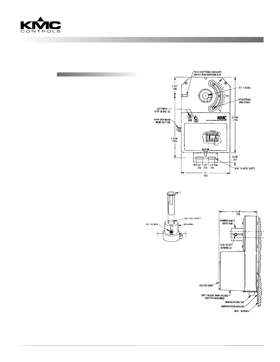
Mounting
The TSP-6001/6051 is designed to mount directly to
a 1/2" diameter shaft, a 3/8" square damper shaft, or
(with an optional HFO-0011 shaft adaptor) a 3/8"
diameter shaft.
Standard Instructions
1. Slide the TSP-60x1 directly onto the 1/2 in.
diameter damper shaft. The shaft must extend a
minimum of 1-3/4 in. from the mounting surface.
(For a 3/8 in. shaft, see
.)
2. Place the non-rotation bracket (supplied) on the
non-rotation tab. Leave a gap of 1/8" between the
bottom surface of the TSP-60x1 and the bracket to
allow for play during operation (see illustration).
3. Attach the non-rotation bracket to the mounting
surface using (2) #8 or #10 self-tapping screws
(not included).
4. Depress the gear disengagement button and:
A. Rotate the drive hub until the indicator stops
at the “90” mark if the damper is clockwise to
close.
B. Rotate the drive hub to the “0” mark if the
damper is counterclockwise to close.
5. Position the damper to full open.
6. Torque the two 5/16-18 set screws 75 to 85 in-lb.
7. Depress the gear disengagement button and
rotate the drive hub/damper to the closed
position.
8. Loosen the adjustable end stop, position against
the damper position indicator, and retighten.
HFO-0011 Adaptor
1. Mount the TSP-60x1 over the 3/8 in. shaft.
2. Slide the HFO-0011 over the shaft into the drive
hub of the actuator.
3. Align the adaptor slots with the set screws.
4. Partially tighten the set screws.
5. Continue with Step 2 under the Standard
Instructions section above.