Wiring, Maintenance, Accessories – KMC Controls MEP-4101 User Manual
Page 2: Specifications, Specifications 2
MEP-4101
2
Installation Guide
© 2012 KMC Controls, Inc.
036-019-03A
KMC Controls, Inc.
19476 Industrial Drive
New Paris, IN 46553
574.831.5250
www.kmccontrols.com
Maintenance
No routine maintenance is required. The motors
are permanently lubricated and all internal gear-
train components are oil-impregnated. Careful
installation will also ensure long term reliability and
performance.
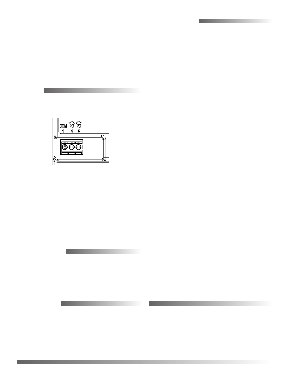
Wiring
Connect the wires to the terminal block and apply 24
VAC (+20%/–15%) power for tri-state operation.
5.313
135
3.844
97.6
1.281
32.5
0.204
0.194
5.18
4.93
LEDs VISIBLE UNDER TRANSLUCENT COVER
GREEN: POWER OPEN (CCW DIRECTION)
RED: POWER CLOSED (CW DIRECTION)
ADJUSTABLE
STOP
1.568
40
[63.5]
2.500
2.600
66
GEAR
DISENGAGEMENT
LEVER
When the actuator reaches the end of rotation, the
motor is disengaged, and (after about five seconds)
the appropriate LED indicator under the translucent
cover illuminates—green for “power open” (CCW)
or red for “power closed” (CW). The LED remains
on until:
• Power to the terminal is simply removed
• Power is switched to the other terminal, and
the actuator starts turning again in the opposite
direction
Accessories
HCO-1151
Weather shield kit
HMO-4001
Non-rotation “T” bracket
HMO-4002
Replacement non-rotation
bracket
Supply Voltage
24 VAC (+20%/–15%), Class 2
Supply Power
2 VA
Control Signal
Tri-state, 24 VAC
Frequency
50/60 Hz
Angular Rotation
0 to 95°, fully adjustable with
mechanical stop
Motor Timing
30 seconds for 90° @ 60 Hz;
36 seconds for 90° @ 50 Hz
Torque
10 in-lb. (1.1 N•m)
Mounting
Direct on 1/4 to 5/8 inch (6 to
16 mm) round or 1/4 to 7/16
inch (6 to 11 mm) square shaft
by adjustable “V” bolt; mini-
mum recommended damper
shaft length is 1-5/8 inches
Connections
Wire clamp type; 14 to 22
AWG, copper
Dimensions
5.3 x 2.6 x 2.5 inches
(135 x 66 x 63.5 mm)
Weight
1 lb. (0.45 kg)
Enclosure
Flame-retardant plastic black
base and translucent cover
Noise Level
< 35 dBA max. at 1 meter
Environmental Limits
Operating
–22 to 140° F (–30 to 60° C)
Shipping
–40 to 176° F (–40 to 80° C)
Humidity
5 to 95% RH (non-condensing)
Specifications
5b. Alternately, insert a single #8 or #10 self-tapping
screw directly into the non-rotation slot. Tighten
the screw only enough to ensure that the screw
will not come out. There should be a bit a play
between the screw and the sides of the slot to help
prevent binding.
6. Evenly tighten the V-bolt nuts 30 to 35 in-lb.
7. If desired, use a 7/64-inch hex key wrench to
loosen and position the end-stop screw.