Wiring, Ste-6014/6017/6018, Ste-6019/6020 – KMC Controls STE-6020 User Manual
Page 2: Maintenance, More information, Important notices
STE-6014/6017/6018/6019/6020 Room Temperature Sensors
2
Installation Guide
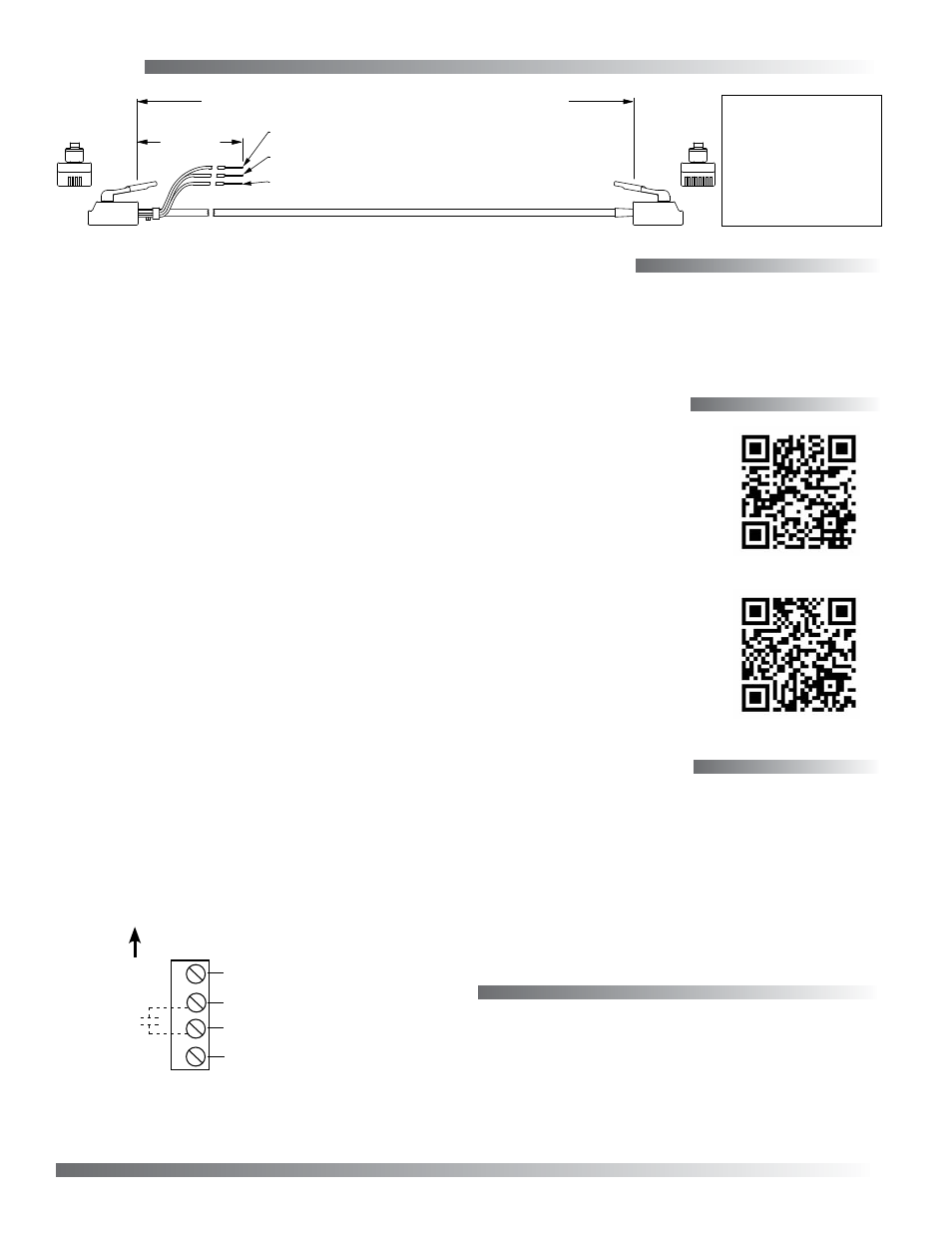
STE-6014/6017/6018
Connecting any of these models to a KMC controller
requires a special cable with (on the sensor end) an
RJ-45 connector and (on the controller end) an RJ-11
connector with an additional three wires (as relevant
to the model) for controller inputs. Purchasing
preassembled cables from KMC is more cost-
effective and reliable than creating custom cables in
the field. Use one of the following cables:
• KMD-5693 = 25 feet
• KMD-5694 = 50 feet
• KMD-5695 = 75 feet
The three additional wire connections to the control-
ler are:
• Orange is the thermistor signal to the controller’s
appropriate input
• Orange/white is the setpoint signal to the con-
troller’s appropriate input
• Green is the supply voltage of 10 VDC to the
STE-6018 LED from an output of the controller
(for the STE-6014/6017, clip or tape the unused
wire)
NOTE: Pressing the push button (not available
on the STE-6014) momentarily shunts the
thermistor for a SENSORON signal (via the
C terminal or orange wire).
KMD-5693 = 25 feet; KMD-5694 = 50 feet; KMD-5695 = 75 feet
1
8
Orange
Wire = Thermistor
Temperature
Signal to Controller
Orange/White
Wire = 0–10K Pot
Setpoint
Signal to Controller
12 inches
5
2
RJ-11 and
Wire Leads
to Controller
RJ-45
to STE
Sensor
Green
Wire = 10 VDC
Supply Voltage
from Controller
(for STE-6018 only; cut or tape back for STE-6014/6017)
RJ-11 RJ-45 Color
(Lead) 8 Orange
7 N.C.
(Lead) 6 Green
3
5
Blue
4
4
Blue/White
5
3
Green/White
2 N.C.
(Lead) 1 Orange/White
(
Cables crossed, 20 AWG
)
Wiring
STE-6019/6020
Common (“Ground”)
Thermistor (10K Ohms)
A
B
C
Potentiometer (0–10K)
(Override
Button)
D
10 VDC LED Supply (from
Controller; for STE-6020 Only)
© 2013 KMC Controls, Inc.
866-019-04C
KMC Controls, Inc.
19476 Industrial Drive, New Paris, IN 46553
574.831.5250
www.kmccontrols.com
More Information
For general product infor-
mation, see the
on the KMC Controls
web site.
For mounting consid-
erations, network con-
nection, controller con-
figuration, programming,
troubleshooting, and other
.
Important Notices
The material in this document is for information
purposes only. The contents and the product it
describes are subject to change without notice.
KMC Controls, Inc. makes no representations or
warranties with respect to this document. In no event
shall KMC Controls, Inc. be liable for any damages,
direct or incidental, arising out of or related to the
use of this document.
Maintenance
Careful installation will also ensure long-term
reliability and performance. Remove dust as neces-
sary from holes in top and bottom. Clean with a soft,
damp cloth and mild soap.
Up (Toward Ceiling at Installation)