KMC Controls STE-6016 User Manual
Installation guide, Room temperature transmitters (with lcd display), Mounting 1
STE-6012/6016 Room Temperature Transmitters
1
Installation Guide
Installation Guide
Room Temperature Transmitters (with LCD Display)
STE-6012/6016
Location and Cover Removal 1
Handy Box Installation (Recommended)
Maintenance 2
More Information 2
Important Notices 2
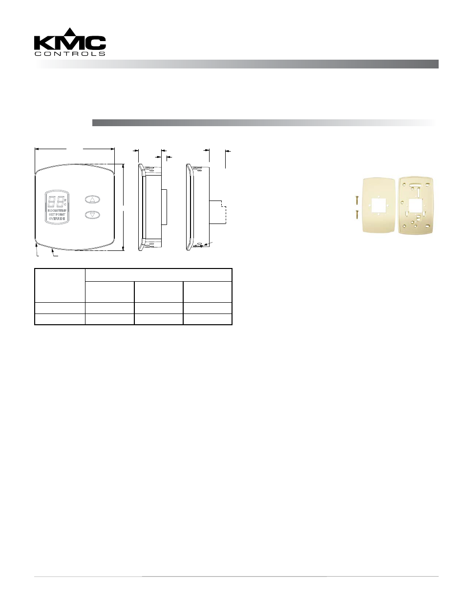
Mounting
All dimensions are in inches
Handy Box Installation (Recommended)
1. Mount an HMO-6036 or
HMO-6036W universal
backplate to the handy
box using the two screws
provided.
2. Remove the cover from
the black base (see the
Location and Cover
Removal section).
3. With the plastic tab button on the bottom, attach
the base to the universal backplate using the two
screws provided.
4. Connect the wiring (see the Wiring section).
5. Reinstall the cover.
Hollow Wall Installation
1. Remove the cover from the black base (see the
Location and Cover Removal section).
2. Using the base as a template, drill two holes
for mounting screws (7/64 inches or 3 mm in
diameter and 1.4 inches, 1-13/32 inches, or 35.6
mm apart) and cut a center hole (size needed is
dependent on model) for the terminal block or
jack.
3. Attach the base to the wall using two #6
self-threading screws. (Plastic anchors are
recommended, and the size of the holes will then
need adjusting.)
4. Connect the wiring (see the Wiring section).
5. Reinstall the cover.
Location and Cover Removal
Install the sensor on an inside wall where it can sense
the average room temperature and be away from
direct sunlight, heat sources, windows, air vents, and
air circulation obstructions (curtains, furniture, etc.). It
can be mounted on a hollow wall or (with a universal
backplate HMO-6036/HMO-6036W) to a 2 x 4 inch
electrical (handy) box.
The cover is held to the black base by three, small,
round pegs that fit in the holes of the cover. The bot-
tom peg is on a tab and snaps into the center bottom
hole.
1. With a small Phillips screwdriver or hex wrench,
press in and hold the plastic tab button that
snaps into the center hole on the bottom of the
cover. Do not use excessive force and deform or
break the tab.
2. Carefully pull the cover from the black base.
2.438
2.250
R 3.094
R 0.187
0.643
STE-6012
0.475
max.
STE-6016
Modular
RJ-45
Jack
Four-pin
EIA-485
PC Data
Port
Clamp
(Screw-type)
Terminals
0.149
Model
Number
Connections
Screw Clamp
Terminals
RJ-45
Connector
EIA-485 Data
Port
STE-6012
X
STE-6016
X
X