Adjustments and calibration, Testing, Maintenance – KMC Controls SSE-2000 Series User Manual
Page 2: More information, Adjustments and calibration 2 testing, More information 2, Caution
SSE-1000/2000 Series
2
Installation Guide
© 2010 KMC Controls, Inc.
651-019-01C
Maintenance
Protect the element from excessive dust during
installation and job construction. Careful installation
will ensure long-term reliability and performance.
For periodic maintenance, check for dust on the
elements. If present, carefully blow dust off the
elements.
Adjustments and Calibration
Each CEP-4000 is calibrated to its SSE series sensor
at the factory. No further calibration is needed. If the
units are replaced or become mismatched, complete
the following steps to recalibrate the controller and
sensor.
1. Connect sensor terminals 1, 2, and 3 to CEP-4000
terminals 1, 2, and 3 respectively. (Connection of a
thermostat to the CEP-4000 is not necessary.)
2. Connect the CEP-4000 to a 24 VAC, –15%/+20%,
50/60 Hz power source (disconnect the power
to the transformer while wiring the CEP).
Connect terminal 9 to the “–”common side of the
transformer, and connect terminal 10 to the “~”
phase side of the transformer.
3. Connect the voltmeter “+” to CEP terminal 2 and
“–” to CEP terminal 4.
4. Ensure zero airflow in the duct or remove the
sensor from the duct and place it in a horizontal
position with zero airflow.
5. Wait 5 minutes for the CEP and SSE units to
stabilize.
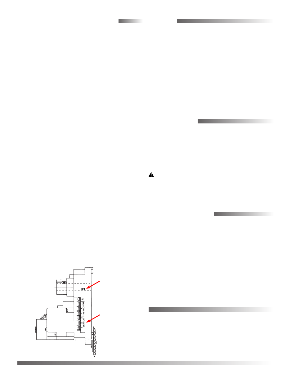
6. Access the trimpot through the slot in the CEP-
4000’s side. The slot is normally covered by a label
and is on the sensor/thermostat connection side
(see illustration below).
7. Adjust the trimpot until the voltmeter reads 9
volts. When the adjustment is made, the voltage
will immediately overshoot and then stabilize.
This establishes the baseline. (See the Voltage/
Velocity Correlation section in the CEP-4000
Application Guide for more information.)
8. Wait an additional 5 minutes for the CEP and SSE
units to stabilize.
9. Readjust if necessary.
KMC Controls, Inc.
19476 Industrial Drive
New Paris, IN 46553
574.831.5250
www.kmccontrols.com
CEP-4000
Trim
Potentiometer
Testing
1. Disconnect ALL wiring from the SSE sensor.
2. Measure resistance between terminals 1 and 3
with an ohmmeter. Resistance should be between
100–400 ohms. If not, replace the sensor and
recalibrate controller to the new sensor. See the
Adjustments and Calibration section.
3. SSE-2000 series sensors have additional terminals
marked “X” and “Y” for use with the heat/cool
changeover relay module. Resistance between
“X” and “Y” should be between 2,000 and 20,000
ohms.
More Information
For specifications, see the SSE-1000/2000 Data Sheet.
For sample applications, see the CEP-4000 Applica-
tions Guide.
Sensor
Connections
CAUTION
To prevent damage to the SSE series sensors, do not
touch or handle the interior wire windings.