Wiring, Maintenance, More information – KMC Controls THE-1105 User Manual
Page 2: Important notices, More information 2 important notices 2, Wiring maintenance, Caution
THE-1105
2
Installation Guide
© 2013 KMC Controls, Inc.
870-019-01G
KMC Controls, Inc.
19476 Industrial Drive
New Paris, IN 46553
574.831.5250
www.kmccontrols.com
Important Notices
The material in this document is for information
purposes only. The contents and the product it de-
scribes are subject to change without notice. KMC
Controls, Inc. makes no representations or warran-
ties with respect to this document. In no event shall
KMC Controls, Inc. be liable for any damages, direct
or incidental, arising out of or related to the use of
this document.
Wiring
Maintenance
Careful installation will also ensure long-term
reliability and performance. Remove dust as neces-
sary from holes in top and bottom. Clean with a soft,
damp cloth and mild soap.
More Information
For controller/software configura-
tion for the humidity input, see
the relevant documentation for
the controller and software. For
controller/software configuration
for the thermistor input as well as
mounting considerations, trouble-
shooting, and other information,
see also the relevant sections in the
For specifications and accessory
information, see the
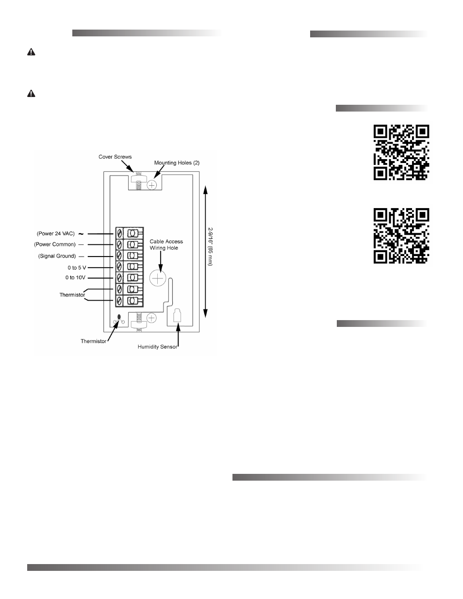
CAUTION
Excess wire inside the THE-1105 may cause
damage to the thermistor. Be careful when
wiring and replacing the unit’s cover.
CAUTION
Use only a 24 VAC, Class 2 transformer for
power.
NOTE: Use 18–22 AWG stranded wire with a
maximum length of 250 feet.
1. Connect the 24 VAC (–15%/+20%, Class 2 ONLY)
transformer, carefully observing the phasing. (See
the wiring diagram.)
2. Connect the humidity transmitter output,
selecting either 0 to 10 VDC and Signal Ground or
0 to 5 VDC and Signal Ground.
3. Connect the temperature sensor (Type II 10K
thermistor) if required.