Wiring, More information, Maintenance – KMC Controls THE-1102 User Manual
Page 2: Important notices, More information 2 maintenance, Important notices 2, Wiring maintenance
THE-1102
2
Installation Guide
© 2013 KMC Controls, Inc.
861-019-01F
KMC Controls, Inc.
19476 Industrial Drive
New Paris, IN 46553
574.831.5250
www.kmccontrols.com; [email protected]
Important Notices
The material in this document is for information
purposes only. The contents and the product it de-
scribes are subject to change without notice. KMC
Controls, Inc. makes no representations or warran-
ties with respect to this document. In no event shall
KMC Controls, Inc. be liable for any damages, direct
or incidental, arising out of or related to the use of
this document.
Wiring
Maintenance
Careful installation will also ensure long-term
reliability and performance. Remove dust as neces-
sary from holes in top and bottom. Clean with a soft,
damp cloth and mild soap.
More Information
For controller configuration of the
humidity input, see the relevant
documentation for the controller
and software. For controller con-
figuration of the thermistor input
as well as mounting considerations,
troubleshooting, and other informa-
tion, see also the relevant sections
in the
.
For THE-1102 specifications and
accessory information, see the
For more information about using
the THE-1102 with the REE-2002,
see the
NOTE: The early version of the THE-1102 had
terminals marked A through F.
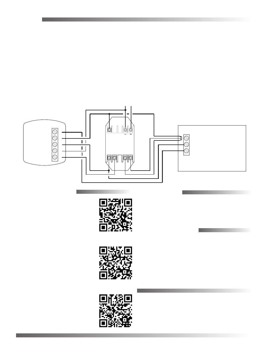
For power, connect the + side of a regulated 10–15
VDC power supply to Terminal “D” and the – side to
“F” (see the terminal diagram).
NOTE: Signal ground and power ground are
connected together internally.
Connect the temperature output (10K thermistor
across Terminals “A” and “C”) to the controller’s
temperature input. (Set the controller’s pull-up resis-
tor accordingly.)
Connect the humidity output (0 to 5 VDC across
Terminals “B” and “C”) to the controller’s humidity
input. (Set the controller’s pull-up resistor accord-
ingly.)
NOTE: The internal thermistor and the 0 to 5 VDC
humidity output have a common signal
ground.
Alternately, use an REE-2002 (shown here but pur-
chased separately). See the
for additional information about power and
humidity output options.
REE-2002
24 VAC
GND
24 VAC
0-5 VDC
0-10
VDC
4-20
mA
F
C
D
B
THE-1102
Humidity Output
(0-5 VDC)
(Without the REE-2002, only the THE-1102’s 0-5 VDC humidity
output and thermistor signal are available to a controller)
Temp. Output
(10K Thermistor)
Signal Ground
– Power Ground
+ 10-15 VDC Power
F
C
D
B
A
Controller
Temp. Input
Signal Ground
Humidity Input*
+
Phase
Neutral
*Load between Humidity Input and Signal Ground
is 250 ohms min. to 650 ohms max. for 4-20 mA
or 1000 ohms min. for VDC