Wiring, More information, Maintenance – KMC Controls THE-1002 User Manual
Page 2: Important notices, More information 2 maintenance, Important notices 2
THE-1002
2
Installation Guide
© 2013 KMC Controls, Inc.
859-019-01I
KMC Controls, Inc.
19476 Industrial Drive
New Paris, IN 46553
574.831.5250
www.kmccontrols.com; [email protected]
Important Notices
The material in this document is for information
purposes only. The contents and the product it de-
scribes are subject to change without notice. KMC
Controls, Inc. makes no representations or warran-
ties with respect to this document. In no event shall
KMC Controls, Inc. be liable for any damages, direct
or incidental, arising out of or related to the use of
this document.
Maintenance
Careful installation will also ensure long-term reli-
ability and performance. Remove dust as necessary
from the sensing tube.
More Information
For controller configuration
of the humidity input, see
the relevant documenta-
tion for the controller and
software. For controller
configuration of the
thermistor input as well as
mounting considerations,
troubleshooting, and other
information, see also the
relevant sections in the
.
For THE-102 specifications
and accessory information,
see the
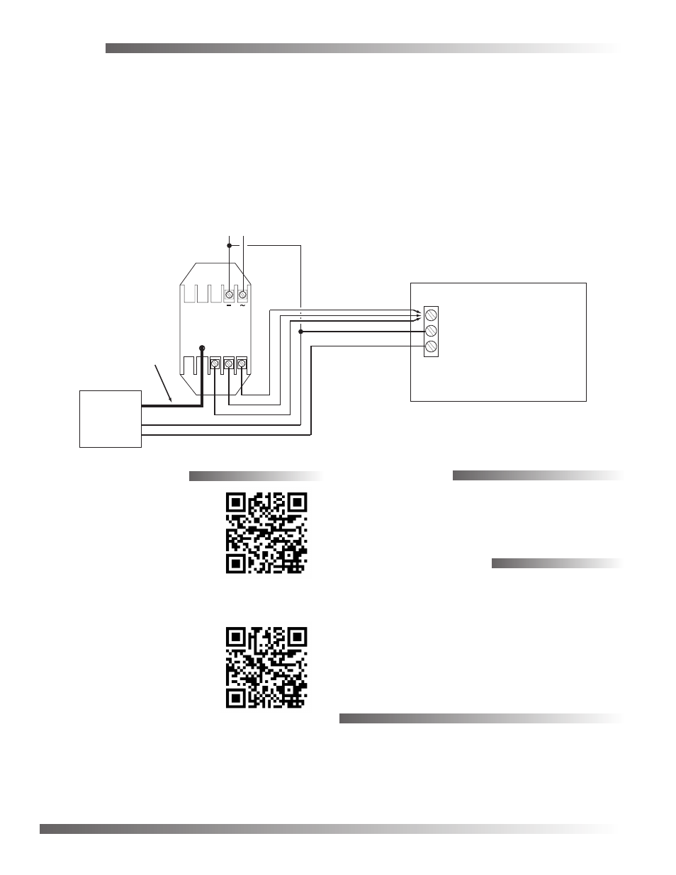
Wiring
Relay
Module
24 VAC
To
Probe
Cable from Humidity
Sensor in Probe
(Do NOT attempt to
shorten or lengthen
this ribbon cable)
10K Ohm
Thermistor Leads
24 VAC
0-5
VDC
0-10
VDC
4-20
mA
Controller
Temperature Input
Signal Ground
Humidity Input*
*Load between Humidity Input and Signal Ground
is 250 ohms min. to 650 ohms max. for 4-20 mA
or 1000 ohms min. for VDC
Phase
Neutral
For power, connect a 24 VAC, Class 2 only, trans-
former (see the diagram).
Connect the desired humidity output (0–5 VDC, 0–10
VDC, or 4–20 mA) from the THE-1002 to the control-
ler’s humidity input. (Set the controller’s pull-up
resistor accordingly.)
NOTE: The thermistor and the humidity output
have a common output signal ground.
Connect the temperature output (thermistor leads)
from the THE-1002 to the controller’s temperature
input. Make wire connections with either butt-splices
or solder. Using wire nuts is not recommended. (Set
the controller’s pull-up resistor accordingly.)
NOTE: The two-wire thermistor leads are polarity
insensitive.
NOTE: The relay module mounted inside the
electrical housing is hard-wired to the
sensing probe. Do not attempt to lengthen
or shorten the prewired ribbon cable.