Range, Bidirectional, Port swap – KMC Controls TPE-1483 Series(2008 and later) User Manual
Page 3: Slow damping, Output reverse, Operation, Calibration, Maintenance, Range 3 bidirectional 3 port swap, Operation 3 calibration 3
TPE-1483 Series Wet-Wet Differential Pressure Transducers
3
Installation Guide
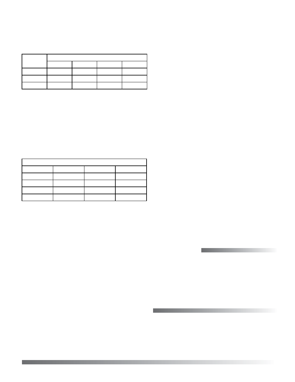
Range
NOTE: Range and Options switches can be
changed while the unit is operating, but
change the Output jumpers only with the
power removed.
Model
0 to x Pressure Range (Switch Position)
1
2
3
4
1483-1
50 psi
25 psi
10 psi
5 psi
1483-2
100 psi
50 psi
20 psi
10 psi
1483-3
500 psi
250 psi
100 psi
50 psi
Bidirectional
This switch changes the range from 0 to full scale
differential pressure to minus full scale to plus full
scale differential pressure. The analog output will
read 1/2 when the differential pressure is zero. The
example below shows the results when a TPE-1483-
22 (0 to 100 psi range) is operated in bidirectional
mode (–100 to 100 psi).
TPE-1483-22 Bidirectional Enabled (Switch to the Right)
High Port
Low Port
4–20 mA
0–5 VDC
100 psi
50 psi
16 mA
3.75 VDC
50 psi
100 psi
8 mA
1.25 VDC
50 psi
50 psi
12 mA
2.5 VDC
100 psi
0 psi
20 mA
5 VDC
Port Swap
This switch reverses the polarity of the pressure
ports. It makes the HIGH port “low” and the LOW
port “high.” This is useful to correct plumbing
errors.
Slow Damping
For surge dampening, this switch provides an
averaging period of 8 seconds instead of the default
4 seconds.
Output Reverse
This switch reverses the output signal polarity. In
reverse mode the analog output is maximum when
the pressure differential is zero and decreases as
pressure increases.
Operation
For normal operation such as 0 to 100 psi, the
pressure applied to the High port must be higher
than the pressure applied to the Low port. If the
pressure connection is reversed then the transmitter
will always output 4 mA or 0 V.
If the Low port is left open to ambient pressure, then
the High port is used to measure a positive pressure
and 0 psi = 4 mA and 100 psi = 20 mA.
For bidirectional operation such as +/–100 psi,
the pressure applied to the High port should be
higher than the pressure applied to the Low port
for a positive output response. Negative pressure is
indicated if the High pressure is less than the Low
pressure. In this case –100 psi = 4 mA and +100 psi =
20 mA. Since the transmitter is linear 0 psi = 12 mA.
Calibration
With both ports open to the ambient pressure or
equalized at 0 pressure:
1. Press and hold the auto-zero button or provide
contact closure between the ZERO and COMMON
terminals for at least 3 seconds.
2. Release the button, and the device will calculate
and store the new zero point.
NOTE: To protect the unit from accidental zeroing
this feature is enabled only when the
detected pressure on both ports is less than
5% of the full range.
© 2014 KMC Controls, Inc.
717-019-06B
KMC Controls, Inc.
19476 Industrial Drive
New Paris, IN 46553
574.831.5250
www.kmccontrols.com
Maintenance
No routine maintenance is required. Each compo-
nent is designed for dependable, long-term reliability
and performance. Careful installation will also
ensure long-term reliability and performance.