Set-up, Configuration, Jumper settings – KMC Controls TPE-1464 Series(2008 and later) User Manual
Page 3: Range, Slow damping, Output reverse, Operation, Calibration, Maintenance, Set-up 3
TPE-1464 Series Gauge Pressure Transducers
3
Installation Guide
Set-Up
Configuration
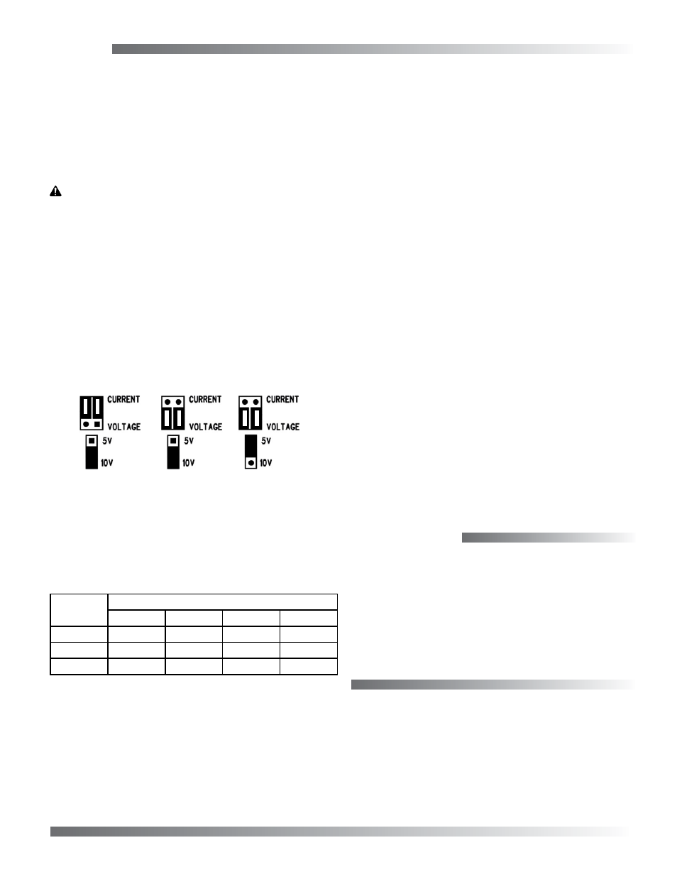
Jumpers and switches are used to select the output
signal type, the input pressure range, and several
options. The device is factory configured to operate
in the 4 to 20 mA output mode but can be changed to
voltage mode by moving the two jumpers from the
CURRENT positions to the VOLTAGE positions.
CAUTION
Change the output jumper positions only while the
power is removed.
Always note the current jumper position before
moving them to the new position. If the jumpers
are rotated 90 degrees and installed incorrectly
the product will not work and damage may occur.
Output Reverse
This switch reverses the output signal polarity. In
reverse mode the analog output is maximum when
the pressure differential is zero and decreases as
pressure increases.
JUMPER SETTINGS
4–20 mA output 0–10 VDC output 0–5 VDC output
Jumper Settings
For voltage/current/range selection, see the illustra-
tion for jumper settings.
Operation
For normal operation such as 0 to 100 psi, the port is
used to measure a positive pressure and 0 psi = 4 mA
or 0 VDC and 100 psi = 20 mA or or 10 VDC (on 10 V
range).
Calibration
With the port open to the ambient pressure or
equalized at 0 pressure:
1. Press and hold the auto-zero button or provide
contact closure between the ZERO and COMMON
terminals for at least 3 seconds.
2. Release the button, and the device will calculate
and store the new zero point.
NOTE: To protect the unit from accidental zeroing
this feature is enabled only when the
detected pressure on both ports is less than
5% of the full range.
© 2014 KMC Controls, Inc.
717-019-03B
KMC Controls, Inc.
19476 Industrial Drive
New Paris, IN 46553
574.831.5250
www.kmccontrols.com
Maintenance
No routine maintenance is required. Each compo-
nent is designed for dependable, long-term reliability
and performance. Careful installation will also
ensure long-term reliability and performance.
Range
NOTE: Range and Options switches can be
changed while the unit is operating, but
change the Output jumpers only with the
power removed.
Model
0 to x Pressure Range (Switch Position)
1
2
3
4
1464-1
100 psi
50 psi
20 psi
10 psi
1464-2
200 psi
100 psi
40 psi
20 psi
1464-3
500 psi
250 psi
100 psi
50 psi
Slow Damping
For surge dampening, this switch provides an
averaging period of 8 seconds instead of the default
4 seconds.