Connections, Adjustments, Calibration – KMC Controls CTC-1622 User Manual
Page 2: Throttling range, Maintenance, Important notices, Additional resources, Connections 2 adjustments 2, Calibration 2
CTC-1621/1622
2
Installation Guide
Connections
The CTC-1611/1612 requires an HFO-0028 tubing
kit.
1. Connect the Main Air to Port M.
2. Connect the Branch Air to Port B.
3. Connect the open side of the Branch Air with
tubing to the final device actuator (DA unit for
the CTC-1621 or RA unit for the CTC-1622).
Adjustments
© 2014 KMC Controls, Inc.
510-019-02B
KMC Controls, Inc.
19476 Industrial Drive
New Paris, IN 46553
574.831.5250
www.kmccontrols.com; [email protected]
Important Notices
The material in this document is for information
purposes only. The contents and the product it de-
scribes are subject to change without notice. KMC
Controls, Inc. makes no representations or warran-
ties with respect to this document. In no event shall
KMC be liable for any damages, direct or incidental,
arising out of or related to the use of this document.
Maintenance
Remove dust as necessary from the slots. Clean the
window with a soft, damp cloth and mild soap.
Care should be taken to keep the unit clean
from dust during installation. Each component is
designed for dependable, long-term reliability, and
performance. Careful installation will also ensure
long-term reliability and performance.
Throttling Range (TR)
Throttling range is the temperature required to
change the thermostat output pressure from 3–15 psi.
All CTC-1600 series thermostats are factory-set for
a 3° F throttling range. The approximate TR setting
is stamped on each lever in both °F and °C. If it is
necessary to change this setting, reverify calibration
after adjustment.
1. Remove the scale plate (see the Scale Plate
section).
2. Slide the black TR adjuster to appropriate value/
location. The hole in the TR adjuster fits a 1/16"
hex wrench. Gently rotate the adjuster back and
forth while sliding. Do not turn excessively!
3. Rotate the TR adjuster back to a “square” position
if needed after adjustment.
4. Reinstall the scale plate.
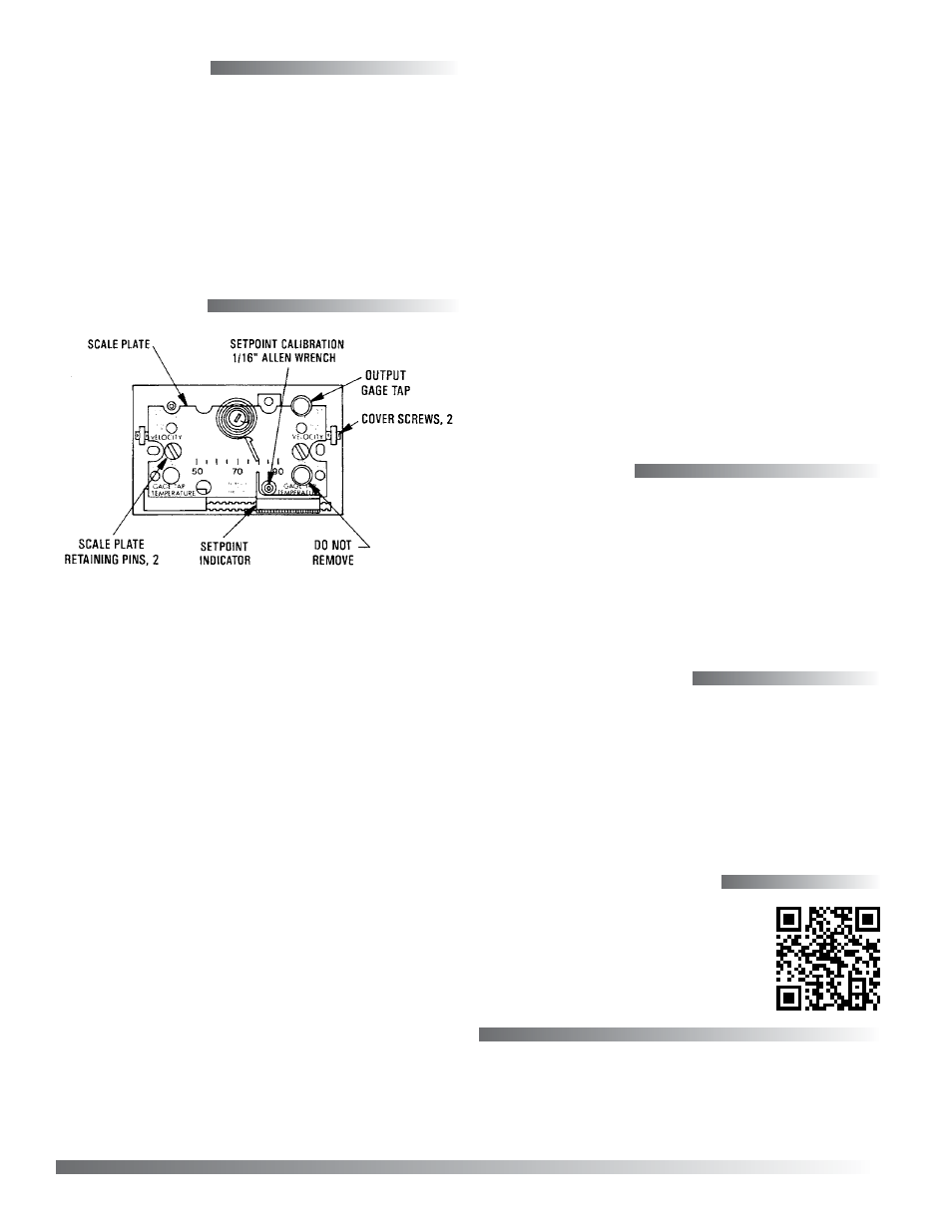
Calibration
These thermostats are factory-calibrated and do not
require further calibration at installation. Should
it be necessary to change calibration, perform the
following steps:
1. Remove the cover and gauge tap rubber cap.
2. Install a gauge on the gauge tap using 3/32" ID
tube.
3. Measure the ambient temperature with an
accurate thermometer.
4. Move the setpoint slider to the measured ambient
temperature.
5. Use a 1/16" hex wrench and turn the calibration
adjustment until the test gauge indicates the
desired pressure. (Clockwise rotation decreases
the output pressure.)
6. Replace the gauge tap rubber cap after
calibrating.
7. Place the setpoint slider to the desired
temperature and replace the cover.
Additional Resources
For specifications and accessories,
on the KMC web site.
NOTE: TR
ADJUSTMENT
NOT SHOWN
(UNDER COVER)