Important notices, Maintenance, Adjustments and calibration – KMC Controls CTE-1101 User Manual
Page 2: Temperature averaging
CTE-1001/1002/1101
2
Installation Guide
© 2011 KMC Controls, Inc.
800-019-02C
KMC Controls, Inc.
19476 Industrial Drive
New Paris, IN 46553
574.831.5250
www.kmccontrols.com, [email protected]
Important Notices
The material in this document is for information pur-
poses only. The contents and the product it describes
are subject to change without notice. KMC Controls,
Inc. makes no representations or warranties with respect
to this document. In no event shall KMC Controls, Inc.
be liable for any damages, direct or incidental, arising
out of or related to the use of this document.
Maintenance
No routine maintenance is required. Each compo-
nent is designed for dependable, long-term reliabil-
ity, and performance. Careful installation will also
ensure long-term reliability and performance.
CTE-1101
Adjustments and Calibration
Upon receipt from the factory, no thermal calibration
should be required.
Flow control points can be calibrated before or after
installation:
1. Verify 9.1 VDC between (+) and (–) terminals. (See
the wiring diagram on the previous page.)
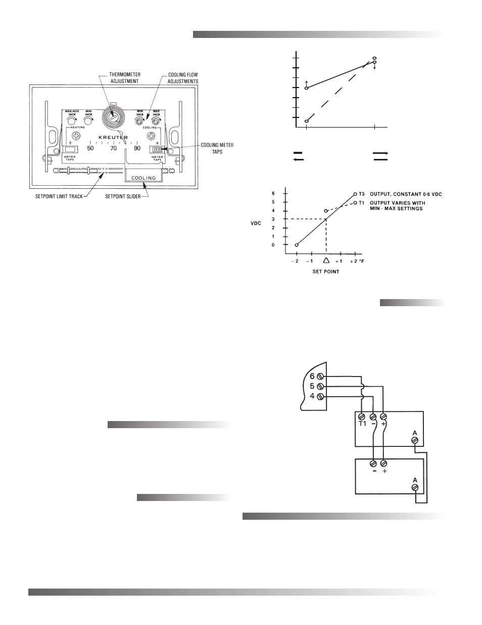
2. Measure T1 output voltage (via the meter taps
and HSO-5001 calibration test leads).
3. Refer to the graphs (at the right) to make
adjustments.
4. Always adjust the minimum flow first.
a. DA Cooling: Setpoint > Room Temp.
b. RA Heating: Setpoint < Room Temp.
5. Always adjust maximum limits to a value higher
than the minimum limits. If in doubt, turn Max.
limit fully clockwise (increase) before proceeding.
a. DA Cooling: Setpoint < Room Temp.
b. RA Heating: Setpoint > Room Temp.
0
1
2
3
4
5
6
-1˚F
+1˚F
CTE-1001 SPACE TEMPERATURE D.A. COOLING
CTE-1002 SPACE TEMPERATURE R.A. HEATING
SETPOINT
T3 OUTPUT, D.A.
T1 OUTPUT, D.A.
∆
T1 & T3
VDC
OUTPUT
CTE-1101
Thermostat
CEP/CSP
Series
Controller-
Actuator
TTE-1001
Remote
Temperature
Transmitter
Temperature Averaging
For temperature averaging on a CTE-1101 (only),
connect the CTE-1101’s A, +, and – terminals to
the respective terminals on the back of the remote
transmitter.