Scale plate, Cover, Connections and wiring – KMC Controls CTE-5100 Series User Manual
Page 2: Connections and wiring 2
CTE-5100 Series
2
Installation Guide
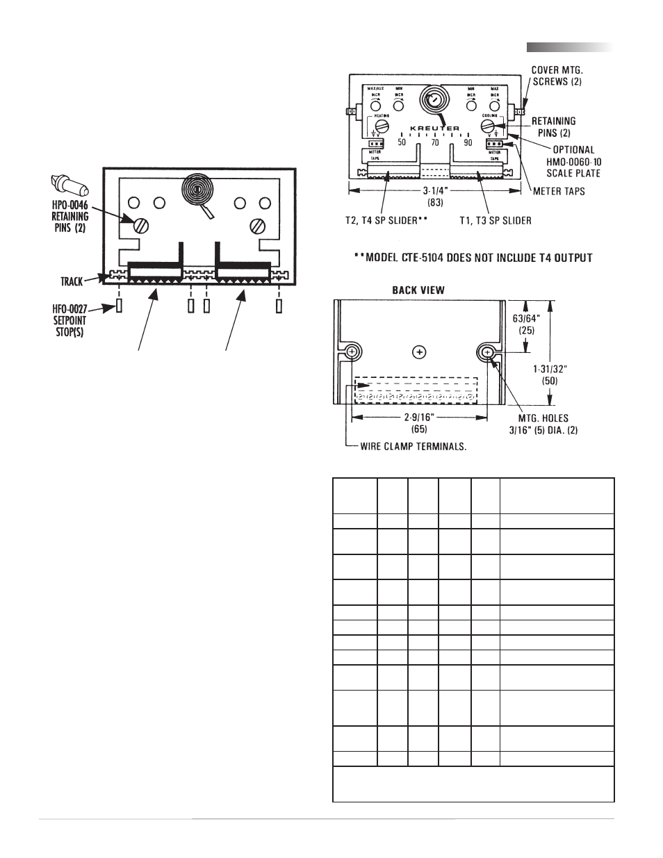
Retaining Pins, Setpoint Stops, and Setpoint Sliders
Scale Plate
1. Install scale plate under the setpoint indicators.
2. Align mounting holes.
3. Insert the two (supplied) HPO-0046 retaining pins
into the holes.
4. Twist pins 1/4 turn to firmly seat.
Connections and Wiring
Terminal CTE-
5101
CTE-
5102
CTE-
5103/
5105
CTE-
5104
Description
V1
X
X
X
Velocity input for read-out
T3
X
X
X
Upper setpoint output
with
out limits
R1
X
X
X
T1 override,
connect to “–” if unused
T1
X
X
X
Upper setpoint output
with limits
+
X
X
X
X
16 VDC power supply input
12V
X
X
X
X
12 VDC power output
A
X
X
X
X
Temp. averaging input
–
X
X
X
X
Ground reference
T2*
X
X
X
Lower setpoint output
with limits*
R2*
X
X
X
T2 override (voltage applied
to R2 subtracts from T2),
connect to “–” if unused
*
T4
X
X
Lower setpoint out
with
out limits
V2
X
X
Velocity input for read-out
*Except CTE-5104, in which
T2 lower setpoint output is without limits.
Also CTE-5104’s
R2 is auxiliary limit trigger, in which voltage above 1
VDC to R2 indexes T1 to the auxiliary flow limit.
Cover
NOTE: When using a blank cover (without a
window), remove the finger pads on the
setpoint sliders. Hold the slider in place,
insert a small flat blade screwdriver into
the slot in the metal slider. Twist the
screwdriver slightly to pop the pad off.
With the window style covers, a symbol-coded label
strip is included to apply to the covers for setpoint
indication.
1. Remove the window from the cover by applying
light pressure on its underside and flexing
upward.
2. Peel off correct identity label from the strip of
labels provided.
3. Position the label on the cover’s recessed area.
4. Snap window back in place.
5. Slide cover onto base.
6. Locate the setscrew on each of the thermostats
short sides.
7. Using a 1/16" hex wrench, turn setscrews outward
CCW until the cover is secure. (Turn setscrews
CW to remove cover.)
(Depth
with
cover,
not
shown)
1-7/8"
(47 mm)
REMOVEABLE SETPOINT ADJUSTER PADS (SEE NOTE)