Specifications, Accessories, Models – KMC Controls BAC-5831 User Manual
Page 2: Operation, Maintenance, Caution
HPO-0070/0071
2
Installation Guide
© 2008 KMC Controls, Inc.
717-019-11A
KMC Controls, Inc.
19476 Industrial Drive
New Paris, IN 46553
574.831.5250
www.kmccontrols.com; [email protected]
Maintenance
No routine maintenance is required. Each component
is designed for dependable, long-term reliability, and
performance. Careful installation will also ensure
long-term reliability and performance.
Operation
Once installed, the suppressor boards require little
user intervention. If the suppressor is damaged
because of a high-voltage transient, causing the
protected circuit to open, simply replace the affected
board.
Specifications
Mounting
Snap Track
Dimensions
2
1
⁄
8
" x
5
⁄
8
" x (3
1
⁄
4
" for HPO-0071
or 4
13
⁄
16
" for HPO-0070) un-
mounted; 2
3
⁄
8
" x 1" x (3
7
⁄
16
" or
5
1
⁄
4
") mounted in Snap Track
Technology
Transorbs
Max. Peak Current 250 A, 1 time (@ 8/20 µs);
125 A, 2 times (@ 8/20 µs)
Voltage
18 Volts
Clamping Voltage 40 Volts @ 8/20 µs
Ambient Limits
Operating
–40° to 185° F (–40° to 85° C)
Shipping
–40° to 185° F (–40° to 85° C)
Humidity
0 to 95% RH, non-condensing
Regulatory
UL 864 Smoke Control Equip-
ment listed (UUKL)
UL 916 Energy Management
Equipment listed
Models
HPO-0070
Twelve-output transient
suppressor board
HPO-0071
Eight-input transient
suppressor board
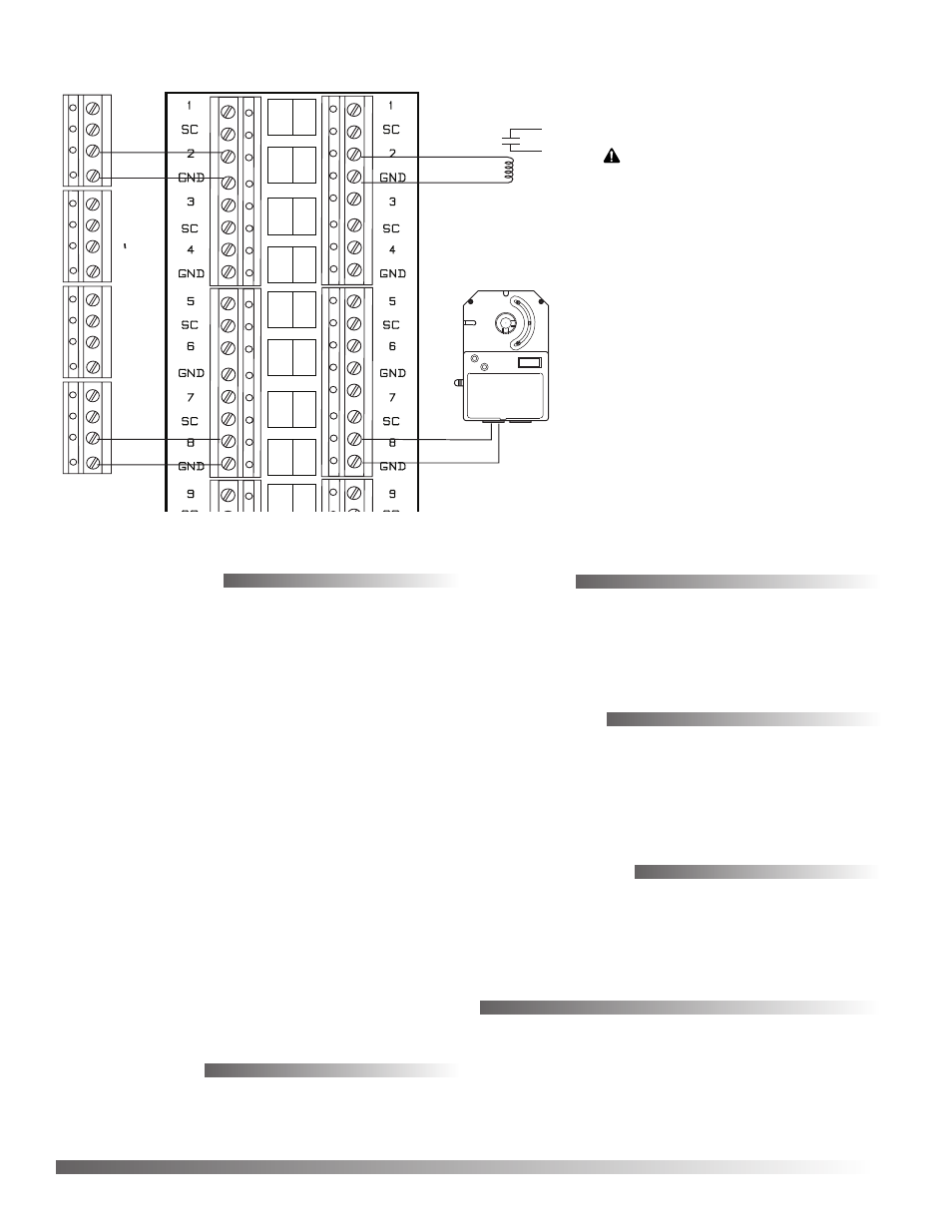
Illustration 3—Output Wiring
Accessories
902-602-08
Replacement terminal block,
eight-pin
��������
����������
�������
�����������
�������������
������������
��������
�������������
���
�
��
�
���
�
��
�
���
�
��
�
���
�
��
�
CAUTION
Connecting 24 volts to an
analog ground will result
in improper operation and
may result in equipment
damage. Use only the relevant
Switched Common (SC)
instead of Ground (GND)
when the HPO-6701 triac and
HPO-6703/6705 relay output
override boards are installed
in a controller. The switched
common terminals are isolated
from the circuit grounds used
for the universal output analog
circuitry in the controller.