Wiring boiler outlet sensors (tekmar 082), Wiring the outdoor sensor (tekmar 070), Terminals 26 to 31 – tekmar 284 Boiler Control User Manual
Page 27: Terminals 17, 19, Mounting the universal sensors
© 2014
284_D - 08/14
27 of 60
A Watts Water Technologies Company
Connect 18 AWG or similar wire to the two terminals provided
in the enclosure & run the wires from the sensor to the
control. Do not run the wires parallel to telephone or power
cables. If the sensor wires are located in an area with strong
sources of electromagnetic interference (EMI), shielded
cable or twisted pair should be used or the wires can be
run in a grounded metal conduit. If using shielded cable,
the shield wire should be connected to the Com terminal
on the control & not to earth ground.
Replace the front cover of the sensor enclosure.
Connect one wire from the outdoor sensor to the Out terminal
17 on the 284.
•
•
•
Connect the second wire to the Com terminal 19.
•
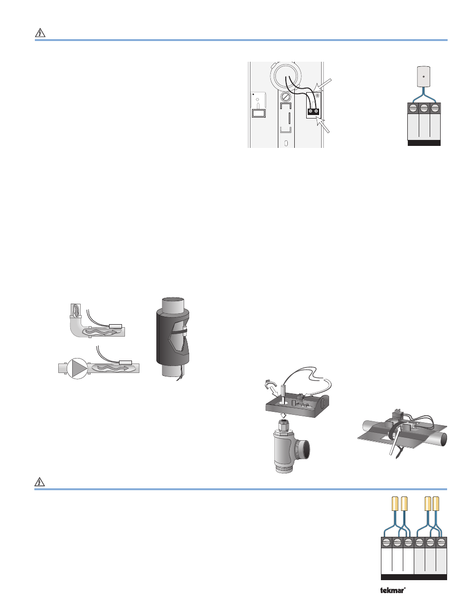
Mounting the Universal Sensors -----------------------------------------------------------------------
-----------------------------------------------------------------------
These sensors are designed to mount on a pipe or in a
temperature immersion well.
The Universal Sensor should be placed downstream of a pump
or after an elbow or similar fitting. This is especially important
if large diameter pipes are used as the thermal stratification
within the pipe can result in erroneous sensor readings. Proper
sensor location requires that the fluid is thoroughly mixed within
the pipe before it reaches the sensor.
Strapped to Pipe
The Universal Sensor can be strapped directly to the pipe
using the cable tie provided. Insulation should be placed
around the sensor to reduce the effect of air currents on the
sensor measurement.
Immersion Well
If a Universal Sensor is mounted onto 1” (25 mm) diameter L
type copper pipe, there is approximately an 8 second delay
between a sudden change in water temperature & the time
the sensor measures the temperature change. This delay
increases considerably when mild steel (black iron) pipe is
used. In general, it is recommended that a temperature well
be used for steel pipe of diameter greater than 1-1/4” (32
mm). Temperature wells are also recommended when large
diameter pipes are used & fluid stratification is present. If the
well is not a snug fit on the sensor tube, use the heat transfer
paste supplied with the product. Apply paste to the sides of the
sensor and place a pea-sized globule on the sensor tip. Push
the sensor into the well and when it bottoms out, press firmly.
The paste will be forced up the sides of the well.
Conduit Connection
The Universal Sensor & Universal Sensor Enclosure 080 (sold
separately) are specifically designed to mount onto a 3/8” (10
mm) ID temperature well that is supplied with an end groove.
To install the well, plumb a ‘T’ into the pipe & fix the well into
the ‘T’. The 080 enclosure has a 7/8” (22 mm) back knockout
that must be removed & fitted over the temperature well. The
Universal Sensor is then inserted into the well & the retaining
clip supplied with the enclosure is snapped onto the well end
groove. If the well has a threaded end, the installer must supply
a standard threaded conduit retaining ring. The two wires from
the sensor are connected to the terminal block provided in
the enclosure. The other side of the terminal block is used to
connect wires from the control.
Bottom of
Enclosure 080
Universal
Sensor
Cable Tie
Sensor
Well
Retaining
Clip
Universal
Sensor
Wiring Boiler Outlet Sensors (tekmar 082)
Terminals 26 to 31
Up to 4 boiler outlet sensors can be wired to the 284. These connections are not polarity sensitive.
Connect one wire from the outlet sensor for boiler 1 to the Boil 1 Out terminal 26.
Connect the second wire from the outlet sensor for boiler 1 to the Com terminal 28.
Repeat for additional boiler outlet sensors using terminal sets 27 & 28, 29 & 31, 30 & 31.
•
•
•
Boil
1
Out
26
Boil
2
Out
27
Com
28
No Power
Com
31
Boil
3
Out
29
Boil
4
Out
30
No Power
(-)
Out
17
Boil
Sup
18
Com
19
Wiring the Outdoor Sensor (tekmar 070)
Terminals 17, 19
Wires from outdoor
sensor to control’s
outdoor sensor and
sensor common
terminals
Sensor is built into
the enclosure