Wiring the input power, Control wiring wiring the primary pumps, Wiring the boiler pumps / valves – tekmar 284 Boiler Control User Manual
Page 23: Terminals 83, 84, Terminals 47 to 50, Terminals 75 to 82
© 2014
284_D - 08/14
23 of 60
A Watts Water Technologies Company
This section explains how to wire individual devices to the Boiler Control 284. For step by step wiring refer to the terminal
number on the right of the page.
Provide a 15 Amp circuit for the input power.
Connect the 115 V (ac) line wire (L) to terminal 83.
Connect the neutral wire (N) to terminal 84.
Connect the ground wire (G) to one of the ground screws provided in the
wiring chamber.
•
•
•
Wiring the Input Power
Terminals 83, 84
Boiler
Control 284
Ground
N
G
L
Power In
L
N
83
84
Control Wiring
Wiring the Primary Pumps
Terminals 47 to 50
Primary pumps requiring up to
230 V (ac) 10 A, 1/2 hp
can be switched through
terminals 47, 48 & 49, 50. If a single power source is used for multiple pumps,
ensure they are not tied together at any point between the pumps & the
control. For simplicity in wiring & troubleshooting, a separate breaker for
each pump is recommended.
For Primary Pump P1 connect the power source line wire (L) to terminal 47.
Connect a wire from terminal 48 to the pump L.
Connect a wire from the pump N back to the power source neutral.
For Primary Pump P2 connect the power source line wire (L) to terminal 49.
Connect a wire from terminal 50 to the pump L.
Connect a wire from the pump N back to the power source neutral.
Ensure grounds are connected in the pump & control wiring chambers.
•
•
•
•
•
•
•
L
N
L
N
N
G
L
N
G
L
Pump
47
48
P1
Primary
Pump
Primary
49
50
P2
Boiler
Control 284
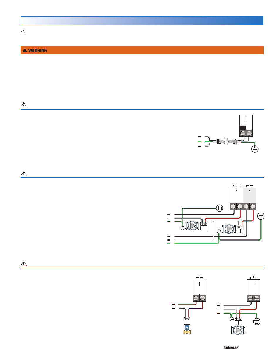
Wiring the Boiler Pumps / Valves
Terminals 75 to 82
Boiler pumps / valves requiring up to
230 V (ac) 5 A, 1/3 hp
can be switched
through terminals 75 to 82. If a single power source is used for multiple
pumps, ensure they are not tied together at any point between the pumps
& the control. For simplicity in wiring & troubleshooting, a separate breaker
for each pump is recommended.
For the Boiler 1 Pump / Valve connect the power source line wire (L) or low
voltage (R) to terminal 75.
Connect a wire from terminal 76 to the device L or R (low voltage).
Connect the N or C (low voltage) back to the power source neutral.
Repeat for additional pumps using the Boiler 2 Pump / Valve to Boiler 4
Pump / Valve terminal sets (77 & 78), (79 & 80) & (81 & 82).
Ensure grounds are connected in the pump/valve & control wiring
chambers.
•
•
•
•
•
N
G
L
L
N
G
Ground
Boiler
Control 284
Boiler 1
75
76
Pump/Valve
Before wiring, ensure all power is turned off & take all
necessary precautions.
Install the supplied wiring compartment barriers by sliding
them into the grooves provided to isolate the low & high
voltage wiring.
Strip all wiring to a length of 3/8 in. or 10 mm for all
terminals.
•
•
•
A circuit breaker or power disconnect that provides power to
the control should be located nearby & clearly labeled.
Refer to the current & voltage ratings at the back of this
brochure before connecting devices to this control.
Only qualified personnel should install or service the
control.
•
•
•
C
R
R
C
Boiler 1
75
76
Pump/Valve