tekmar 284 Boiler Control User Manual
Page 18
© 2014
284_D - 08/14
18 of 60
A Watts Water Technologies Company
Pump Operation
Primary Pump Operation -------------------------
-------------------------
The control includes two primary pump outputs with capability
for sequencing. There is pump enable setting for each primary
pump in the Setup menu. When both primary pumps are set
to Auto, primary pump sequencing is activated. Primary pump
1 & 2 are operated in stand-by mode when pump sequencing
is activated.
The running times of the primary pumps are logged in the
Monitor Menu. To reset these values back to zero, select
“Clear” while viewing this item.
Operation of the primary pump(s) is determined from the
Application Mode & the presence of an appropriate call.
Application Mode: Outdoor Temperature Reset (RSET)
Heat Call from Contact Closure.
Heat Call from tN4 Device & that zone’s thermostat has H1
Pump set to On. tN4 thermostats also include a thermal
actuator setting which can delay the primary pump for 3
minutes to allow thermal actuators to open.
Setpoint Call from Contact Closure & Primary Pump during
Setpoint operation set to ON.
DHW Call & the Primary Pump during IDHW operation set
to ON.
Application Mode: Setpoint (SETP)
Setpoint Call from Contact Closure & Primary Pump during
Setpoint operation set to ON.
DHW Call & the Primary Pump during IDHW operation set
to ON.
Application Mode: Energy Management System (EMS)
Heat Call from Analog Input Signal.
DHW Call & the Primary Pump during IDHW operation set
to ON.
Setpoint Call from Contact Closure & Primary Pump during
Setpoint operation set to ON.
Application Mode: Building Automation System (BAS)
BAS Setpoint Pump Call.
Flow Proof Call -----------------------------------
-----------------------------------
The control includes a flow proof call in order to prove flow
once a primary pump has turned on. In order for boiler plant
operation to commence, the proof call must be present. A flow
proof call is required at all times during pump operation.
Once a primary pump contact is turned on, a flow proof call
must be present before the flow proof delay has expired.
The flow proof call feature is enabled by setting the DIP switch
to the External Flow Proof position.
The flow proof call feature can only be used when the
control is configured to operate the primary pump for
all loads.
If there are multiple loads (e.g. Heat Call and DHW Call)
and the primary pump is disabled for DHW operation, then
the control cannot provide flow proving and the feature
must be disabled. In this case, the flow proof feature must
be obtained through another control such as the Pump
Sequencer 132.
•
•
•
•
•
•
•
•
•
•
A flow proof call can be provided in two ways:
Contact Closure
A dry contact or 24 V (ac) signal is applied across the Flow
Proof Call terminals 1 & 2.
A contact closure can come from a flow switch, pressure
differential switch, current sensing or power sensing device.
ΔP
Pressure Differential Switch
FS
Flow Switch
KW
Power Sensing Device
Amp Current Sensing Device
Analog Flow Sensor
A 4-20 mA style flow sensor can be used to both monitor &
prove flow. The Flow Sensor item in the Setup Menu must be
set to ON to enable the flow sensor to provide monitoring. The
Flow Rate 4 mA and Flow Rate 20 mA items in the Setup Menu
configure the flow range for the flow sensor being used.
To enable the flow proof feature, the Flow Proof item in the Setup
Menu must be set to a flow percentage. The flow percentage is
the percentage of full flow (dependant on the configured flow
range) that must be achieved within the flow proof delay time
to prove flow. If the flow sensor is not required to prove flow,
the Flow Proof item must be set to OFF.
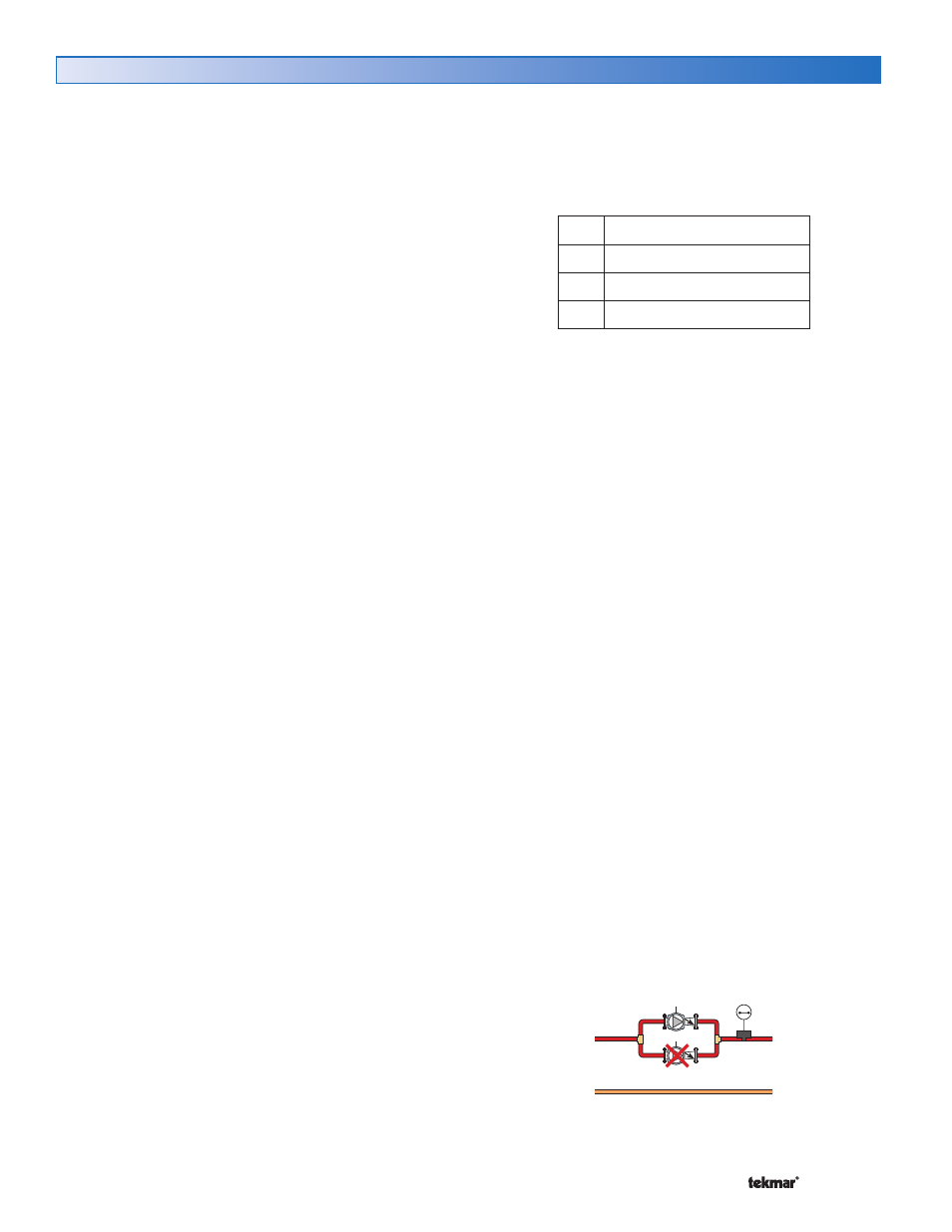
Stand-by Operation ------------------------------
------------------------------
The control only operates one primary pump at a time. A
flow proof device can be used to detect when stand-by pump
operation is required.
When an appropriate Call is registered, the lead pump is
activated, & the control waits for flow to be established within
the flow proof delay time.
If no flow is established, the lead pump is de-activated, the
lag pump is activated & the control waits again for the flow
to establish within the flow proof delay time.
If no flow is established with the lag pump, the control
will make a second attempt to prove flow with the pumps,
starting with the lead pump. If flow cannot be proved after
the second attempts, the control stops operation until the
error is cleared. Verify that the pumps & flow proof device
are working correctly before clearing the error.
If the lead pump establishes flow, & fails during operation,
the lag pump is activated.
If at any time, one or both pumps fail to prove flow, an error
message is displayed.
Normal Operation
OFF
ON
•
•
•
•
•