Installation, Important safety information, Radio frequency interference installation location – tekmar 284 Boiler Control User Manual
Page 22: Figure 1, Figure 2, 259 mm) screw hole dimensions, Custom panel or electrical box wall or panel door
© 2014
284_D - 08/14
22 of 60
A Watts Water Technologies Company
Installation
The installer must ensure that this control & its wiring are
isolated &/or shielded from strong sources of electromagnetic
noise. Conversely, this Class B digital apparatus complies
with Part 15 of the FCC Rules & meets all requirements of
the Canadian Interference-Causing Equipment Regulations.
However, if this control does cause harmful interference to
radio or television reception, which is determined by turning
the control off & on, the user is encouraged to try to correct
the interference by re-orientating or relocating the receiving
antenna, relocating the receiver with respect to this control,
&/or connecting the control to a different circuit from that to
which the receiver is connected.
Cet appareil numérique de la classe B respecte toutes les exi-
gences du Règlement sur le matériel brouilleur du Canada.
Radio Frequency Interference
Installation Location
When choosing the location for the control, consider the
following:
Keep dry. Avoid potential leakage onto the control.
RH 90% to 104°F (40°C).
Non-condensing environment.
Do not expose to operating temperatures beyond 32-104°F
(0-40°C)
Provide adequate ventilation.
Keep away from equipment, appliances or other sources of
electrical interference.
•
•
•
•
Provide easy access for wiring, viewing, & adjusting the
display screen.
Mount approximately 5 ft. (1.5 m) off the finished floor.
Locate the control near pumps &/or zone valves if possible.
Provide a solid backing to mount the enclosure to. For
example: plywood, studs, etc
Use the conduit knockouts provided on the upper, lower,
back & sides of the enclosure.
•
•
•
•
•
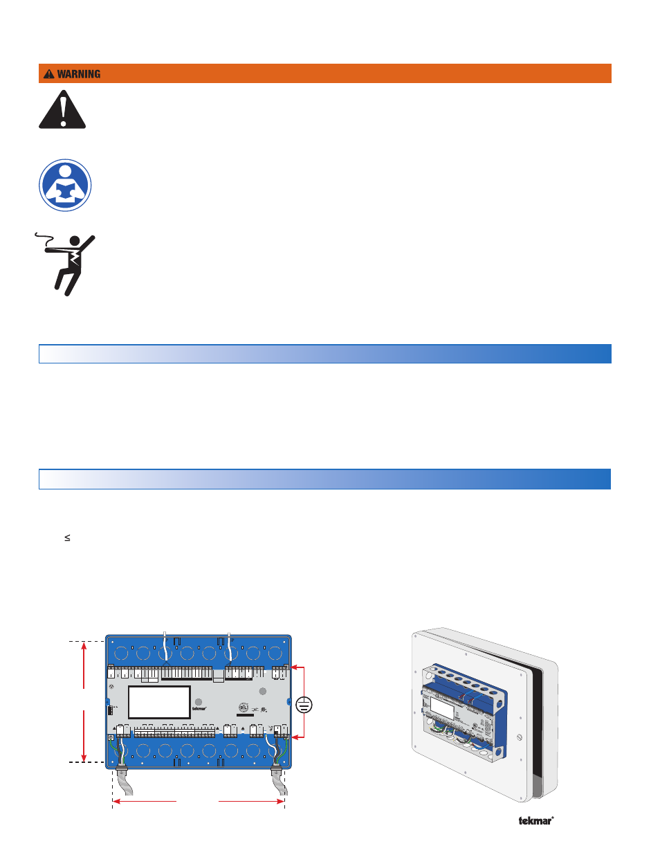
Figure 1
1
2345
Temperature Sensors - Do Not Apply Power
tekmarNet Communication
C3
C2
C0
C1
H70
19
C
75
76
Valve
77
78
79
80
81
82
Pump
Power In
L
N
DHW
Alert
45
46
Auxiliary
43
44
Pump
47
48
P1
Pump
Primary
Primary
49
50
P2
Pump /
Boiler 1
85
86
83
84
20V
11
dc
5V
dc
Out In Out In
In
Vdc
14
+
+
Gnd
15
mA
12
13
+
EMS
16
Out
17
Boil
Sup
18
Com
19
Boil
Ret
Boil
In
20
DHW
21
Com
22
Vent
23
24
25
Boil
1
Out
26
Boil
2
Out
27
Com
Com
28
Com
31
Boil
3
Out
29
Boil
4
Out
30
tN4
32
33
Bus b
tN4
34
35
Bus 1
tN4
36
37
Bus 2
tN4
38
39
Bus 3
Boiler
Boiler
Boiler
Boiler
Flow Proof
1
2
Call
C.A. Proof
3
4
Call
Heat
5
6
Call
DHW
7
8
Call
Setpoint
9
10
Call
40
41
BACnet IP
42
External Flow Proof / Off
External C.A. Proof / Off
Off / Exercise
Setback / Off
51 52
Mod
Boiler 1
53 54
Stage 1
Stage 2
55
56
+
-
Mod
Stage 1
Stage 2
+
-
Mod
Stage 1
Stage 2
+
-
Mod
Stage 1
Stage 2
+
-
57 58
Boiler 2
59
60
61
62 63 64
Boiler 3
65
66
67
68
69
70
Boiler 4
71
72
73
74
tektra 1056-01
For product literature:
www.tekmarControls.com
Disconnect All Power
Before Opening
Designed and
assembled in Canada
Meets Class B: Canadian
ICES & FCC Part 15
Signal wiring must be
rated at least 300 V.
Boiler Control 284
Four tN4, BAS, Four Boiler, DHW & Setpoint
Manual
Override
Home
I
I
Input Power:
115 V (ac) ±10%, 60 Hz, 18 VA
Primary Pump Relays:
230 V (ac), 10 A, 1/2 hp
Boiler & DHW Pumps:
230 V (ac), 5 A, 1/3 hp
Boiler Stage, Auxiliary &
Alert Relays:
230 V (ac), 5 A, 1/6 hp
Calls: 24 V (ac) or Short
I
B
A
Gnd
+
–
–
–
RS485
Flow
Sensor
Pressure
Sensor
WARNING
Valve
Pump /
Boiler 2
Valve
Pump /
Boiler 3
Valve
Pump /
Boiler 4
7
1
/
8”
(181 mm)
Ground
Screws
10
3
/
16”
(259 mm)
Screw hole
Dimensions
Figure 2
Custom Panel
or Electrical Box
Wall or Panel Door
To avoid serious personal injury and damage to the equipment:
It is the installers responsibility to ensure that this control
is safely installed according to all applicable codes and
standards.
Improper installation and operation of this control could result
in damage to the equipment and possibly even personal
injury or death.
This electronic control is not intended for use as a primary
limit control. Other controls that are intended and certified
as safety limits must be placed into the control circuit.
Do not attempt to service the control. There are no user
serviceable parts inside the control. Attempting to do so
voids warranty.
•
•
•
•
Important Safety Information
It is your responsibility to ensure that this control is safely installed according to all applicable codes and standards.
tekmar is not responsible for damages resulting from improper installation and/or maintenance.
Read Manual and all product labels BEFORE
using the equipment. Do not use unless
you know the safe and proper operation
of this equipment.
Keep this Manual available for easy access
by all users.
Replacement Manuals are available at
tekmarControls.com
•
•
•
Disconnect all power before opening the
control.
•