Specifi cations 12 – Sound Devices 788T User Manual
Page 172
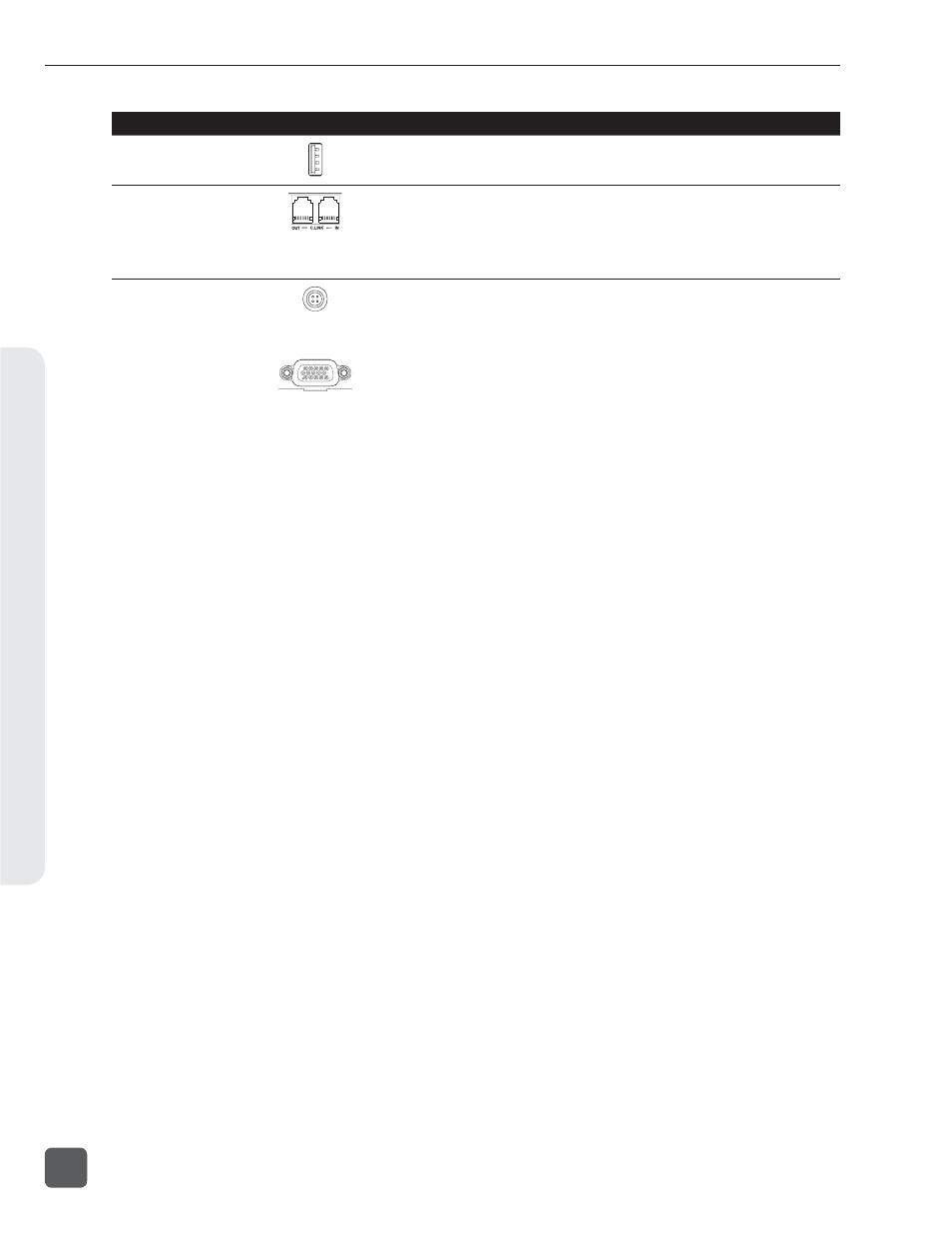
Connector Pin
Assignments
Notes
USB-A Keyboard Input
center pin – signal
sleeve – ground
For use with USB Keyboards only. Data transfer is not
supported.
C. Link In / Out
1 – +3.3 V
2 – Tx (output)
3 – ground
4 – Rx (input)
5 – WC in
6 – TC in
Not a telephone jack! Used for Multi-Unit Linking and to
connect to CL-1 Keyboard and Remote Roll Accessory
and CL-2 Remote Fader. C. Link In is disabled when the
Setup Menu Connection Mode is set to Connect to Wave
Agent.
Hirose 4-pin
DC Input
1 – ground
2 – not connected
3 – not connected
4 – DC (+)
Charging characteristics defined by user in the Setup
Menu.
DE-15
Multi-Function Connector
AES I/O, GPIO, PWR
1 – AES 3,4 Input (+)
2 – AES 1,2 Input (+)
3 – AES 5,6 Output (+)
4 – AES 7,8 Input (+)
5 – AES 5,6 Input (+)
6 – EXT DC (-) Ground
7 – EXT DC (-) Ground
8 – LOGIC Output
9 – LOGIC Input
10 – +10V to 18V DC
11 – AES 3,4 Input (-)
12 – AES 1,2 Input (-)
13 – AES 5,6 Output (-)
14 – AES 7,8 Input (-)
15 – AES 5,6 Input (-)
The D-Sub connector provides 8 channels of balanced
AES input, 2 channels of AES outputs, GPIO and External
DC powering and is therefore ideal as a single umbili-
cal connection between the 788T and an external digital
mixer. Mates with Sound Devices XL-88.
788T/788T-SSD User Guide and Technical Information
164
v. 3.02
Features and specifications are subject to change. Visit www.sounddevices.com for the latest documentation.
Specifi
cations
12