Hardw are controllers 10 – Sound Devices 788T User Manual
Page 133
The Com Input source is defi ned in the Setup Menu option COMMS: INPUT SOURCE as:
• Disabled,
• Built-In,
• or, External (Input 8)
The selected source serves as the send for the Slate system. At Factory Default, the Com Send Source
is disabled. When set to disabled the Slate button is disabled. The Com Send Source shares Input 8’s
signal path. When the Slate is active the Input 8 destinations will be silent. The audio performance of
the 788T’s Built-In Mic is not suitable for critical recording applications.
The Com Send Source shares Input 8’s signal path. This allows for fl exible routing of the Com send source
for all communication systems. However, this does mean that whenever a communication system is active
the Input 8 routing destinations receive the Com Send signal.
To use an external microphone as a Com Mic follow these steps.
1. Enter the Setup Menu option COMMS: INPUT SOURCE.
2. Select the External (Input 8) option. A Notice appears reminding the user that the Slate and
Comms use input 8’s signal path. Press the check mark to continue.
3. Connect an audio source that is to be used as the Com Mic to the TA3 Input 8 on the 788T.
4. Slide the Input 8 Selector Switch to the right to enter the Input 8 Sett ings Window.
5. Setup the input accordingly. That is, choose input type, phantom power, etc... The Input-to-
Track routing for Input 8 is unavailable when set as the Com Mic.
6. Set the trim level of the External Com Mic using the 788T Input 8 Front Panel Gain Control.
7. See Slate Mic Routing and Slate Mic Level for additional setup details.
Slate Mic Routing
The Slate Mic signal can be sent to any Track, Output, or Headphone monitor from the Setup Menu
option COMMS: ROUTING. When the Slate Mic is activated, the Com Mic signal overrides the pro-
gram feed of these destinations. At Factory default, the Slate Mic is routed to all tracks, outputs, and
headphone monitors.
To route the Slate Mic to select destinations follow these steps.
1. With a CL-8 connected, enter the Setup Menu option COMMS: ROUTING.
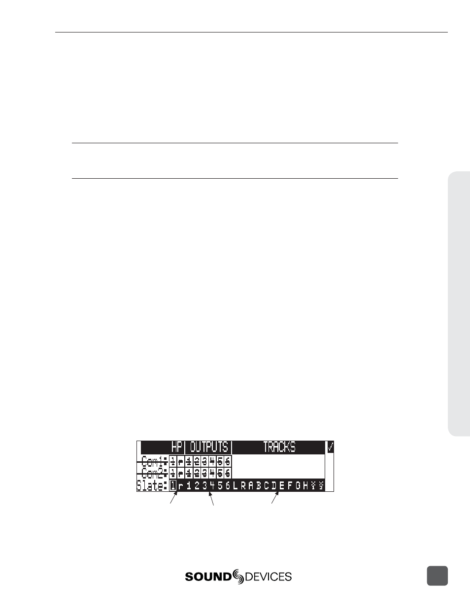
2. Using the Rotary Switch, scroll through the available destinations. The lower case lett ers
represent headphone montiors, the numbers represent outputs, and the capitalized lett ers
represent tracks.
Lower-case letters
represent Headphone
Monitors
Upper-case
letters represent
Tracks
Numbers
represent
Outputs
Hardw
are Controllers
10
788T/788T-SSD User Guide and Technical Information
125