Hardw are controllers 10 – Sound Devices 788T User Manual
Page 123
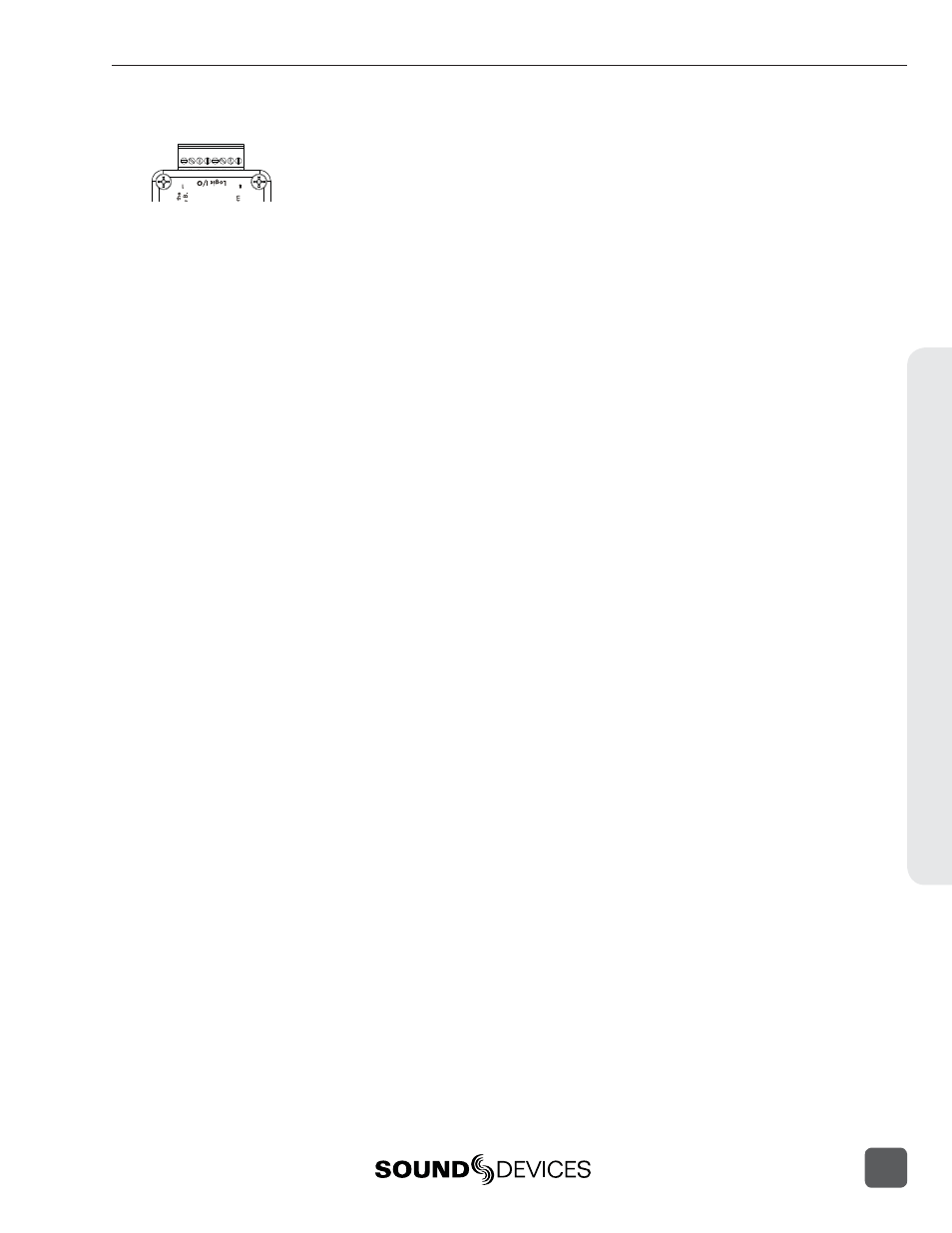
CL-1 Logic Inputs and Outputs
Identical to shortcuts assigned to computer keyboard key sequences, the CL-1 has six contacts that
can be programmed to perform Setup Menu items or control the record, play, and stop functions of
the recorder. A switch connected between the assigned pin and ground (pin-7) will form a circuit.
Closing the circuit will activate the programmed action.
The Logic pins on the CL-1 can be set individually as either a switch-closure input or a switch clo-
sure output. The inputs and outputs are “logic low” devices, meaning that to turn “on” an input, it
must be connected to ground (zero volts). Likewise, when an output is “on”, it puts out 0 volts and
when it is “off”, it puts out +5 volts.
Logic Inputs
Confi gured as a switch-closure input, a pin can be connected to a switch that a user has wired to
assigned contact. This switch can then trigger the 788T to begin recording. Other functions can be
assigned as well from the Setup Menu. The switch-closure on a given pin of the CL-1 can be thought
of as just another key on the keyboard. Anything that can be assigned to a key can also be assigned
to a switch.
To confi gure a pin as an input, navigate to KEYBOARD/LOGIC IN: ASSIGN in the Setup Menu. Select
a new SHORTCUT number, then locate the Login inputs amongst the assignable keys. Choosing
CL1 LOGIC IN 1
would correspond to pin 1 on the CL-1, CL1 LOGIC IN 2 would correspond to
pin 2 on the CL-1, and so on. After a Logic input is selected, assign the desired action that the Logic
input will control.
Logic Outputs
Confi gured as a switch-closure output, the CL-1 can drive LEDs, relays, or any other sort of device
which will accept a TTL-level or similar input. For example, the CL-1 can drive a big red LED con-
nected via a series resistor between the +5V output and a switch-closure output and light up when-
ever the recorder is put into record mode.
To confi gure a pin as an output, go to CL-1: LOGIC OUT ASSIGN in the Setup Menu. The
Logic Pin number is on the left hand side (“00”, “01”, etc). Each of these pins can be as-
signed to undefi ned, Stop, Play, Record, or Pause. Note that if a pin is assigned to be both
an input (via the KEYBOARD/LOGIC IN: ASSIGN Setup Menu) and an output (via the
CL-1: LOGIC OUT ASSIGN
Setup Menu), the pin will automatically default to an output.
Hardw
are Controllers
10
788T/788T-SSD User Guide and Technical Information
115