Banner PresencePLUS P4 Series User Manual
Page 124
If MULTIPLE is chosen from the drop-down list, then click Edit Selections to select more than
one port.
•
• Click View Settings to display the configuration of the connection.
• Data can be sent through 11 different communication connections: one connector for the serial
connection, and 10 sockets (1 to 10) through the Ethernet connector.
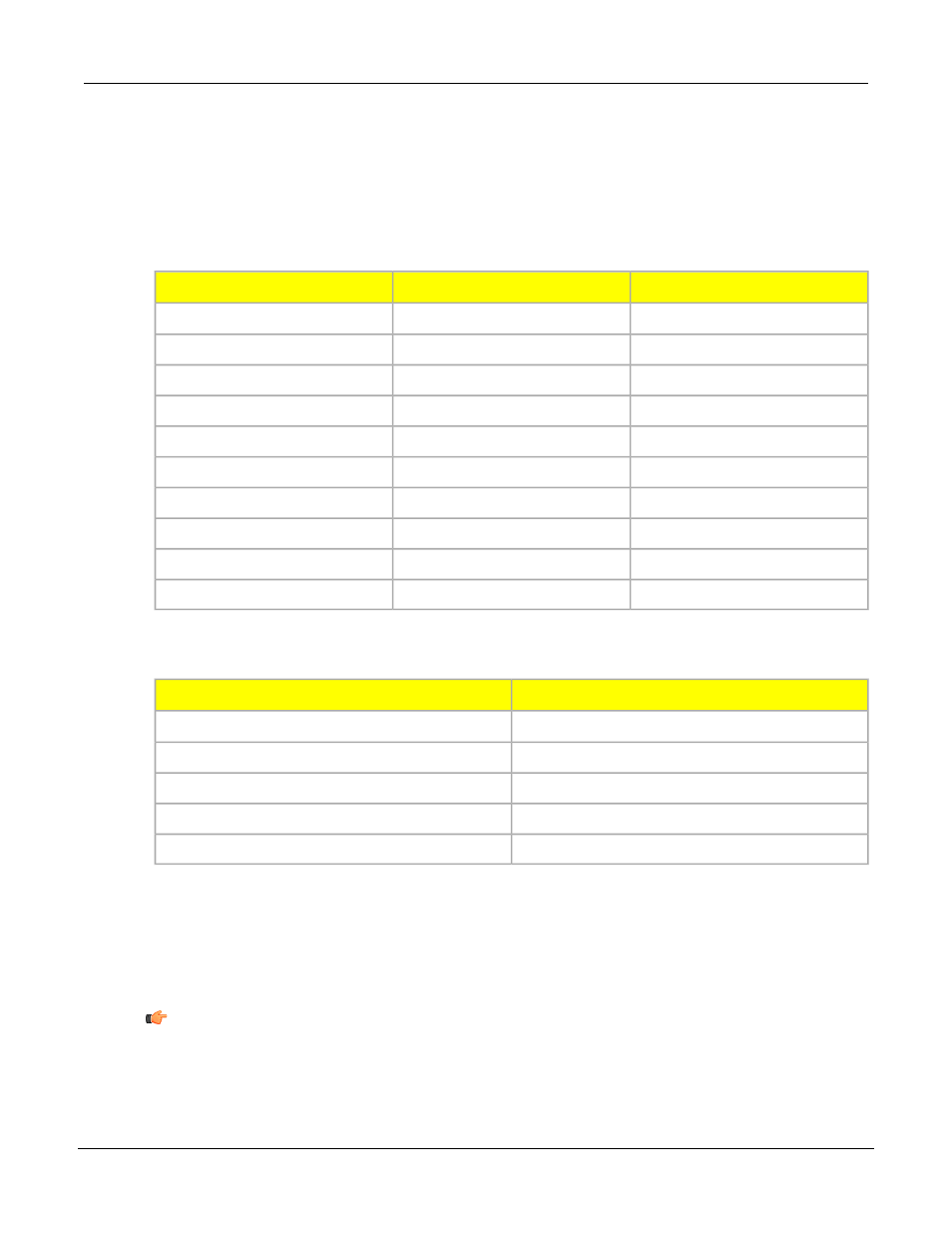
• The 10 Ethernet sockets are comprised of the Sensor IP address and port number. The table
below lists the default Ethernet socket addresses.
Port
Default IP Address
Socket
20,000
192.168.0.1
1
20,001
192.168.0.1
2
20,002
192.168.0.1
3
20,003
192.168.0.1
4
20,004
192.168.0.1
5
20,005
192.168.0.1
6
20,006
192.168.0.1
7
20,007
192.168.0.1
8
20,008
192.168.0.1
9
20,009
192.168.0.1
10
• The serial port is the RS-232 connector (Pins 1, 9, and 10) on the Sensor. The deafult settings
for the serial port are listed below.
Default Setting
Attribute
115200
Baud Rate
8
Data Bits
None
Parity
1
Stop Bit
None
Flow Control
3. Format the ASCII string of data (in the Format field).
• Choose a Delimiter and Start and End strings.
• Check the Enable Labels box to add the names for data being sent.
Allowable ASCII string options are shown below.
Note: Start and End strings can now accept ASCII Hex values, and the following special
characters: "\r", "\n", "\t".
P/N 000000
Banner Engineering Corp. - Minneapolis, MN USA - www.bannerengineering.com
Tel: 763.544.3164
124
7/2009
PresencePLUS Software Tools