2 software overview – Banner PresencePLUS P4 EDGE 1.3 Series User Manual
Page 12
STP25 — 7.6 m (25')
DB9P30 — 9 m (30')
*The Sensor can be connected to the PC via a serial cable or an Ethernet network; Ethernet provides faster
communication.
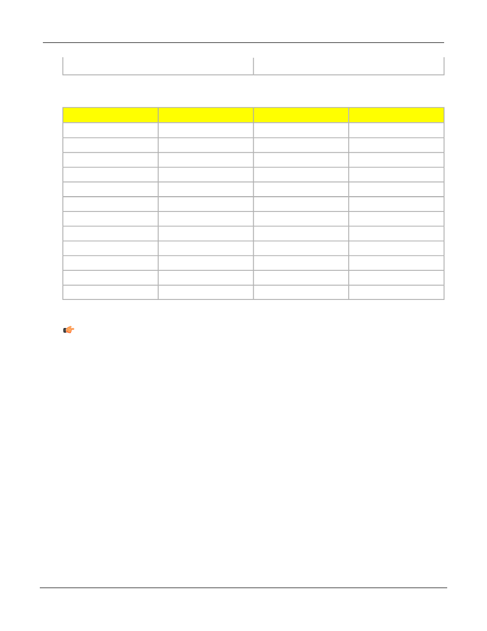
Direction
Description
Wire Color
Pin #
Output
RS-232 TX**
Yellow
1
Input
Remote Teach
Gray
2
Input
Product Change
Orange
3
Input
External Trigger
Pink
4
In/Out
Discrete I/O #1
Black
5
In/Out
Discrete I/O #2
Red
6
In/Out
Discrete I/O #3
White
7
In/Out
Discrete I/O #4
Light Blue
8
Input
RS-232 RX**
Violet
9
Output
RS-232 Signal Ground**
Green
10
Input
Common (Signal Ground)
Blue
11
Input
10-30V dc
Brown
12
** These three wires make up the RS-232 serial connection.
Note: All unused inputs and outputs should be connected to ground if configured as PNP, and
connected to +24V dc if configured as NPN. Serial input pins should be connected to ground.
2.2 Software Overview
The PresencePLUS application window is shown below.
P/N 000000
Banner Engineering Corp. - Minneapolis, MN USA - www.bannerengineering.com
Tel: 763.544.3164
12
7/2009
System Description