Usb ports – Rockwell Automation 2711PC-xxxx PanelView Plus 6 Compact Terminals User Manual User Manual
Page 126
126
Rockwell Automation Publication 2711PC-UM002B-EN-P - April 2014
Chapter 6
Connections and Communication
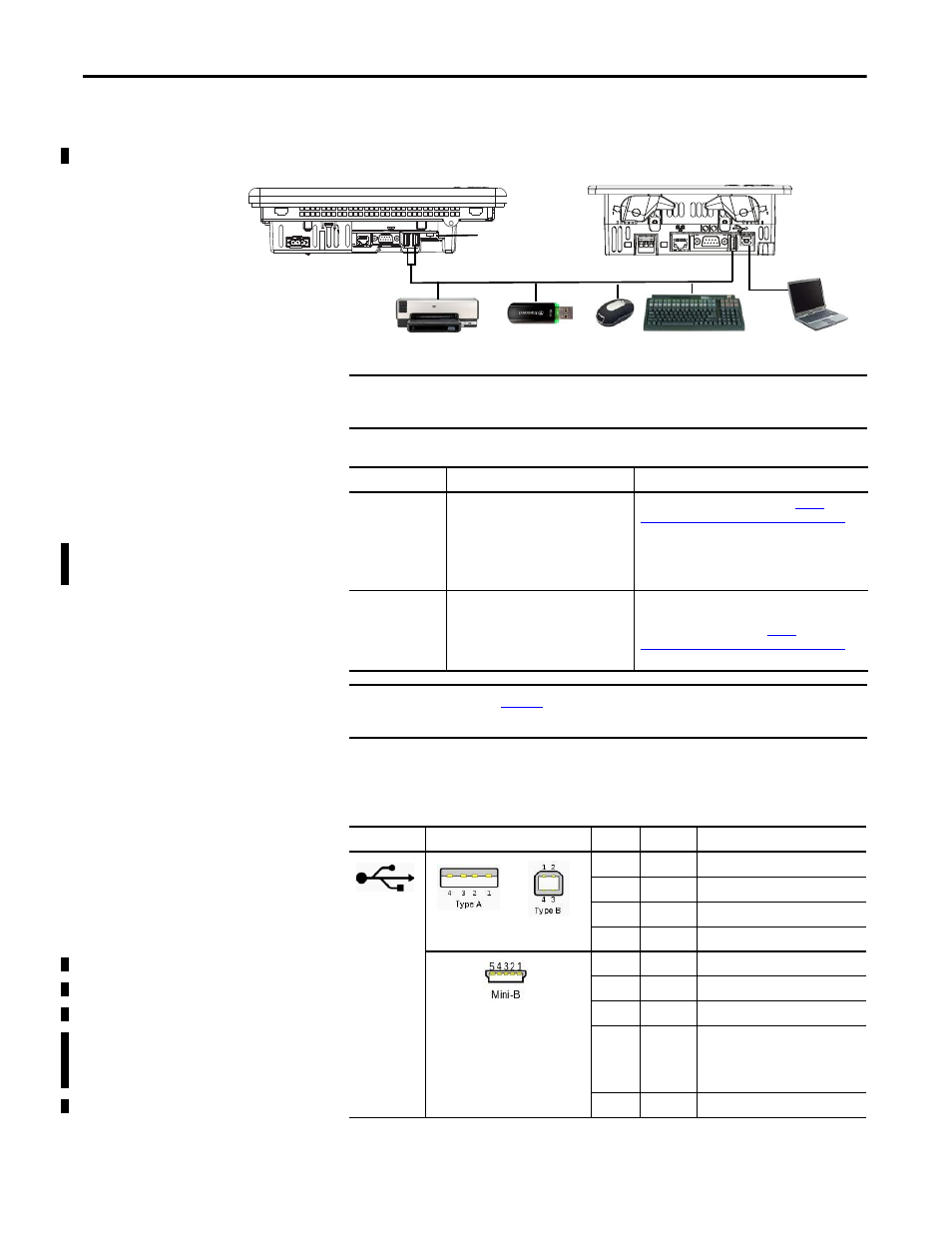
USB Ports
The terminals have one USB 2.0 host port and one USB 2.0 device port.
Figure 10 - USB Ports
The USB ports are identified by a USB icon. Each USB host port supports 0.5 A
at 5V DC. Connected USB devices must not exceed this power load.
USB Host Port
USB Device Port
Mini USB Device Port
USB Host Ports
1000 Terminal
400 or 600 Terminal
IMPORTANT
The USB host and device ports are intended only for temporary use and must
not be used for runtime operations.
Table 39 - USB Device Support
USB Port Type
Supported USB Devices
Tips
Host Ports (type A)
• Keyboard or mouse, HID devices with
native device drivers
• USB drives for external storage
• Supported printers
• Cameras, modems, and bar code
readers
For list of compatible devices, go to:
and search the Knowledgebase for ID 115072.
USB drive volumes are named USB Storage, USB
Storage2,... USB drive partitions are managed by
Storage Manager in the Control Panel.
Device Port (type B)
Host computer with the USB remote
RNDIS network device driver installed.
For details on how to install the USB remote NDIS
driver on your computer and configure the terminal
for the USB connection, go to
and search the Knowledgebase for ID 115608.
IMPORTANT
for information on using the USB host ports and USB
peripheral devices in hazardous locations.
Table 40 - USB Connector Pinouts
USB Icon
USB Ports
Pin
Signal
Description
1
VCC
+5V
2
D-
Data -
3
D+
Data +
4 GND
Ground
1
VCC
+5V
2
D-
Data -
3
D+
Data +
4
ID
Distinguishes host connection from
slave connection:
• Host: connected to signal ground
• Slave: not connected
5
GND
Ground