Using plcć2 logical data addressing – Rockwell Automation 1775-S5_SR5,D17756.5.5 User Manual PLC-3 FAMILY I/0 User Manual
Page 77
Addressing DH and DH+ Data Transfers
Chapter 5
5-3
The S5 and SR5 scanners offer four different addressing methods for use in
DH and DH+ assignment commands:
PLC-2 Logical Data Addressing
PLC-3 Logical Binary Addressing
Logical ASCII Data Type Addressing
Logical ASCII Word Range Addressing
Although the scanner can transmit and receive any of these addressing
methods, not all remote stations are able to interpret these methods.
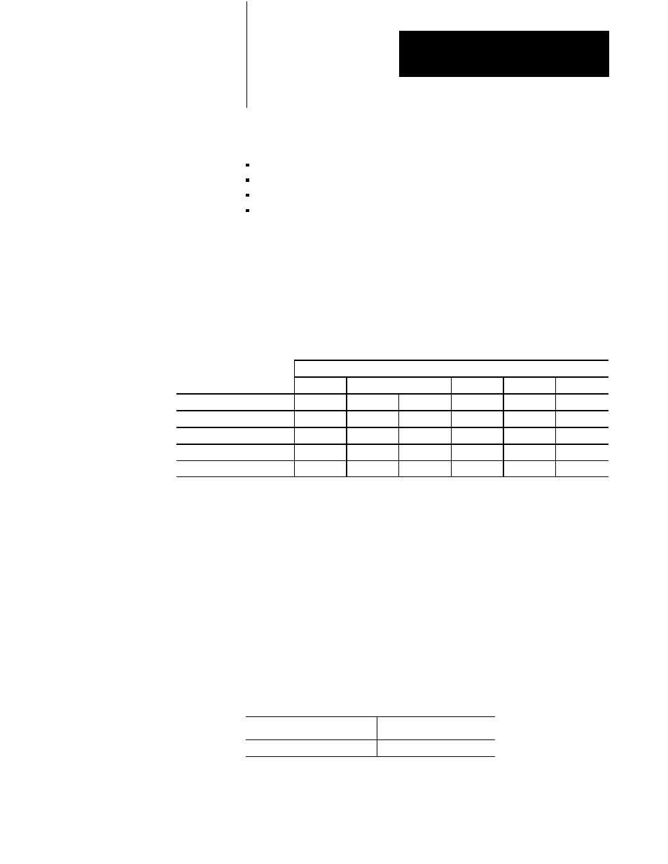
Table 5.A indicates which addressing methods are accepted by
other controllers.
Table 5.A
Acceptable Addressing Methods
Accepted by Receiving Station
PLCĆ3
Addressing
PLCĆ2
KA
S5
PLCĆ4
PLCĆ5
PLCĆ5/250
PLCĆ2 Logical Data
X
X
X
X
X
X
PLCĆ3 Logical Binary
--
X
X
--
--
--
Logical ASCII Data Type
--
--
X
--
X
X
Logical ASCII Word Range
--
--
X
--
X
X
A PLC-2 logical data address references a dedicated file in the remote
station. This addressing method simply provides an offset into this PLC-2
data table or PLC-2 compatibility file. The offset is interpreted as octal if a
leading zero is included, otherwise the scanner interprets the number as
decimal.
The receiving station must be able to interpret this form of addressing (see
Table 5.A).
Addressing Words
To address a group of consecutive words in the remote stations memory,
use the following format:
Format:
Example:
offset, size
$047,20
Using PLCĆ2 Logical Data
Addressing