Binary command language appendix a, Response block – Rockwell Automation 1775-S5_SR5,D17756.5.5 User Manual PLC-3 FAMILY I/0 User Manual
Page 136
Binary Command Language
Appendix A
A-8
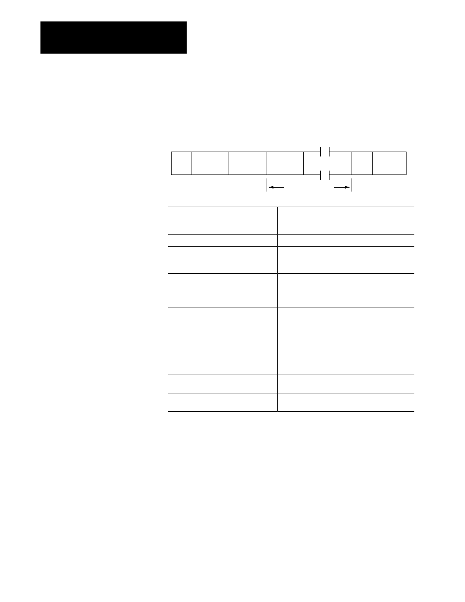
Response Block
With the exception of the CCR response, all responses from the scanner to
the master are in the form of a response block. The response is always
structured as follows:
ETX
Checksum
STX
(02)
Response
Block Seq
Count (03)
response buffer
Response
Data Buffer
Size
Response
Code
Response Data
Command:
Description:
STX (start of text)
the first byte of the control block (02 hex).
Response block sequence count
Response block sequence count (0 to 7F hex).
Response buffer size
Number of bytes to follow in the response buffer.
The buffer includes all bytes between this buffer
size byte and the ETX.
Response code
This byte contains the scanner's reaction to the
previous master's command in the form of a
response code. Table A.C outlines the response
code possibilities.
Response data
The response data includes response parameters
associated with the previous command as received
from the master. When the response data contains
data in word format, the lower byte is sent first.
Important:
The scanner can send multiple
responses in one response buffer provided that
each response has all necessary parameters.
ETX (End of text)
Following the response data buffer is the ETX code
(03 hex).
Checksum
The last byte is a checksum which adds from the
STX (02) through ETX (03) inclusively.