Module tags for 1732e-of4m12r – Rockwell Automation 1732E-OF4M12R ArmorBlock Dual-Port EtherNet/IP 4-Point Analog Input/Output User Manual
Page 87
Rockwell Automation Publication 1732E-UM005A-EN-E - July 2012
79
Module Tag Definitions Appendix C
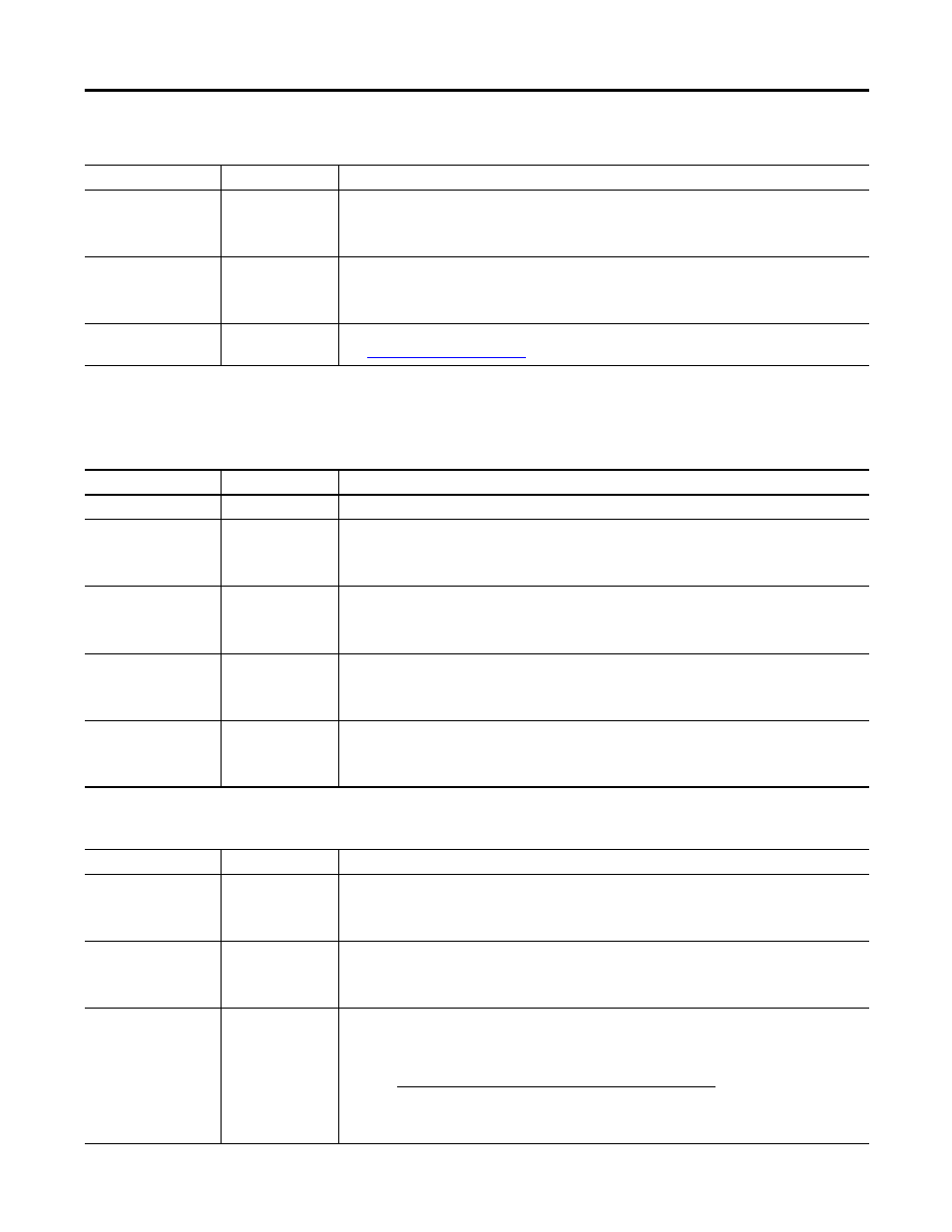
Module Tags for 1732E-OF4M12R
C.Ch0LimitAlarmLatch
C.Ch1LimitAlarmLatch
C.Ch2LimitAlarmLatch
C.Ch3LimitAlarmLatch
SINT
Enables latching for the process alarms. Latching causes the process alarms to remain set until an
unlatch service is explicitly sent to the channel or alarm.
C.Ch0AlarmDisable
C.Ch1AlarmDisable
C.Ch2AlarmDisable
C.Ch3AlarmDisable
SINT
Disables all alarms for the channel:
0 – Alarms are not disabled
1 – Alarms are disabled
C.RealTimeSample
INT
Configures real-time sampling on a module-wide basis.
See
for more information.
Configuration Tags (1732E-IF4M12R)
Tag Name
Data Type
Definition
Input Tags (1732E-OF4M12R)
Tag Name
Data Type
Definition
I.Fault
DINT
Collection of all module level fault bits.
I.Ch0Fault
I.Ch1Fault
I.Ch2Fault
I.Ch3Fault
BOOL
Individual channel fault status bit. Indicates a ‘hard’ fault has occurred on the channel that means:
calibration is ongoing; or if an input, an overrange or underrange condition is present; or if an output, a
low or high clamp condition is occurring. These bits also are set by the controller if communication is
lost with the I/O module.
I.Ch0Calibration
I.Ch1Calibration
I.Ch2Calibration
I.Ch3Calibration
BOOL
Indicates if calibration is currently in progress on a channel.
I.Ch0LAlarm
I.Ch1LAlarm
I.Ch2LAlarm
I.Ch3LAlarm
BOOL
Low alarm bits that set when the input signal moves beneath the configured low alarm trigger point,
Ch<0...3>LAlarmLimit. Remains set until the input signal moves above the trigger point, unless latched
via Ch<0...3>LimitAlarmLatch, of the low alarm trigger point.
I.Ch0HAlarm
I.Ch1HAlarm
I.Ch2HAlarm
I.Ch3HAlarm
BOOL
High alarm bit that sets when the input signal moves above the configured high alarm trigger point,
Ch<0...3>HAlarmLimit. Remains set until the input signal moves below the trigger point, unless latched
via Ch<0...3>LimitAlarmLatch.
Configuration Tags (1732E-OF4M12R)
Tag Name
Data Type
Definition
C.Ch0FaultValue
C.Ch1FaultValue
C.Ch2FaultValue
C.Ch3FaultValue
INT
Defines the value, in counts, the output should take if a communication fault occurs when the
ChxFaultMode bit is set.
Where: x = output channel.
C.Ch0ProgramValue
C.Ch1ProgramValue
C.Ch2ProgramValue
C.Ch3ProgramValue
INT
Defines the value, in counts, the output should take when the connection transitions to Program mode
if the ChxProgMode bit is set.
Where: x = output channel.
C.Ch0LEngineering
C.Ch1LEngineering
C.Ch2LEngineering
C.Ch3LEngineering
INT
The low engineering value helps determine the engineering units the signal values scale into. The low
engineering term corresponds to the low signal value. The scaling equation used is as follows:
Data =
(Signal-LowSignal)(HighEngineering-LowEngineering)
High Signal - Low Signal
+ Low Engineering