Ethernet connector, Power connectors – Rockwell Automation 1732E-OF4M12R ArmorBlock Dual-Port EtherNet/IP 4-Point Analog Input/Output User Manual
Page 19
Rockwell Automation Publication 1732E-UM005A-EN-E - July 2012
11
Install Your ArmorBlock Module Chapter 2
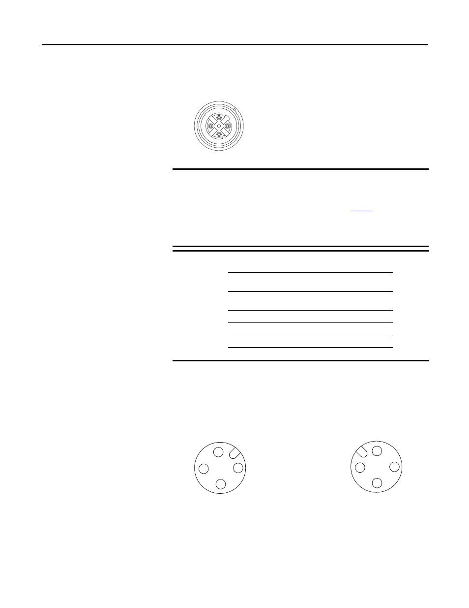
Ethernet Connector
D-Code Micro Network Female Connector
Power Connectors
Attach the mini-style 4-pin connector to the mini-style 4-pin receptacle as shown
below.
Micro-style 4-Pin Input Male Receptacle
The power required by the module is based on a 4-pin micro-style connector
system. Power can be daisy chained through the module either left to right or
right to left. The standard configuration is with Module/Auxiliary power
entering the module on the left connector.
IMPORTANT
Use the 1585D–M4DC–H: Polyamide small body unshielded mating
connectors for the D-Code M12 female network connector.
Note that the distance between the center of each Ethernet connector
is 16.2 mm (see Mounting Dimensions on
Rockwell Automation recommends the use of suitable cable based on
this measurement. Some of the recommended cables are 1585D-
M4TBJM-x and 1585D-M4TBDM-x for daisychains.
IMPORTANT
Use two twisted pair CAT5E UTP or STP cables.
4
2
3
1
5
(View into connector 1)
Pin 1M12_Tx+
Pin 2 M12_Rx+
Pin 3 M12_Tx-
Pin 4 M12_Rx-
Pin 5 Connector shell shield GND
44808
D-Code
M12 Pin
Wire Color
Signal
8-way Modular
RJ45 Pin
1
White-
orange
TX+
1
2
White-green
RX+
3
3
Orange
TX-
2
4
Green
RX-
6
1
4
3
2
3
4
1
2
45764
(View into receptacle)
Pin 1 Auxiliary power+
Pin 2 Module power+
Pin 3 Module power-
Pin 4 Auxiliary power-
45763
Male Input
Female Output