Rockwell Automation 1732E-OF4M12R ArmorBlock Dual-Port EtherNet/IP 4-Point Analog Input/Output User Manual
Page 35
Rockwell Automation Publication 1732E-UM005A-EN-E - July 2012
27
Configure Your Analog Input and Output Modules with RSLogix 5000 Software Chapter 3
1.
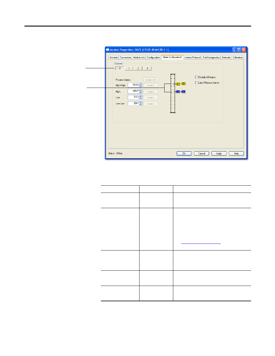
Choose from the options on the Alarm Configuration tab.
Click Channel button to set limits
and alarm configuration for each
of the 4 channels.
Use the sliders to set limits. HH
slider sets High High limits; HI
sets High limits; LL for Low Low;
and LO for Low.
Alarm Configuration tab
Field
What to do
Description
Channel
Select a push button
to correspond to a
channel (0…3)
Click the channel that is being configured.
Process Alarms
Type a value for each of the four alarm trigger
points that alert you when the module has
exceeded these limitations.
You also can use the respective slider icon to set a
trigger value.
The Unlatch buttons are enabled only when the
module is online.
See
for more
information.
High High
Choose from
-32,768...32,767
Select a value so that any value out of range in this
field causes a profile validation error. This value
also appears in the HH slider on
this dialog.
High
Choose from
-32,768...32,767
Select a value so that any value out of range in this
field causes a profile validation error. This value
also appears in the HI slider on this dialog.
Low
Choose from
-32,768...32,767
Select a value so that any value out of range in this
field causes a profile validation error. This value
also appears in the LO slider on this dialog.