Understanding the configuration signature, Configuration via the logix designer application, For in – Rockwell Automation 1756-L7x GuardLogix 5570 Controllers User Manual
Page 65
Rockwell Automation Publication 1756-UM022A-EN-P - November 2012
65
Add, Configure, Monitor, and Replace CIP Safety I/O
Chapter 5
Delay. This method can be used on an input or output connection. After the
system has been run for an extended period of time through its worst-case loading
conditions, record the Maximum Observed Network Delay.
The Network Delay Multiplier can be approximated by the following equation:
[Maximum Observed Network Delay + Margin_Factor]
÷
RPI
Understanding the
Configuration Signature
Each safety device has a unique configuration signature, which defines the
module configuration. The configuration signature is composed of an ID
number, date, and time, and is used to verify a module’s configuration.
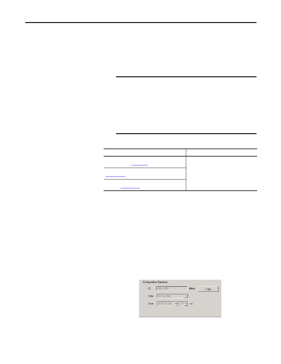
Configuration via the Logix Designer Application
When the I/O module is configured by using the Logix Designer application, the
configuration signature is generated automatically. You can view and copy the
configuration signature via the Safety tab on the Module Properties dialog box.
Figure 20 - View and Copy the Configuration Signature
EXAMPLE
Calculate the Network Delay Multiplier from Maximum
Observed Network Delay
If:
RPI = 50 ms
Maximum Observed Network Delay = 20 ms
Margin_Factor = 10
Then, the Network Delay Multiplier equals:
[20 + 10]
÷
50 = 60%
Table 18 - Additional Resources
Resource
Description
GuardLogix 5570 Controllers Systems Safety Reference
Manual, publicat
Provides information on calculating reaction times.
Guard I/O DeviceNet Safety Modules User Manual, publication
Guard I/O EtherNet/IP Safety Modules User Manual,
publication