Determine if you can use autoscan, How autoscan effects your network, Review how autoscan effects your network – Rockwell Automation 1769-SDN Compact I/O DeviceNet Scanner Module User Manual User Manual
Page 38
38
Publication 1769-UM009E-EN-P - August 2009
Chapter 4 Automatically Configure a DeviceNet Network
Determine If You Can
Use AutoScan
Make sure your network meets the following requirements to use this chapter:
• The scanner’s I/O allocation size is configured to accommodate the
input and output data sizes of all devices on your DeviceNet network.
The default AutoScan setting allocates a 4-byte entry in both the input
and output memory maps in the scanner for each slave device detected
on the network. This default size is chosen to accommodate the default
Logix native data size of 32 bits, that is a DINT.
If you use a device that sends more than 4 bytes of input or output data,
for example, an E3 Solid State Overload Relay (catalog number
193-ECxx), you must change the I/O allocation size.
• You are using the CompactLogix 1769-SDN DeviceNet scanner with
firmware revision 4.1 or greater.
If your network does not meet the requirements listed above, then use
and
to configure your network and control your devices.
How AutoScan Effects
Your Network
As you use AutoScan, keep the following in mind:
Consideration
Description
AutoScan clears the current
configuration.
With AutoScan, the scanner automatically sets up communication with the devices on your DeviceNet
network. When you turn on the AutoScan option, the scanner removes any previous configuration that
was done to the scanner.
AutoScan allocates a fixed
memory size for each device.
At its default setting, AutoScan allocates 1 DINT of input memory and 1 DINT of output memory for
each device on the DeviceNet network.
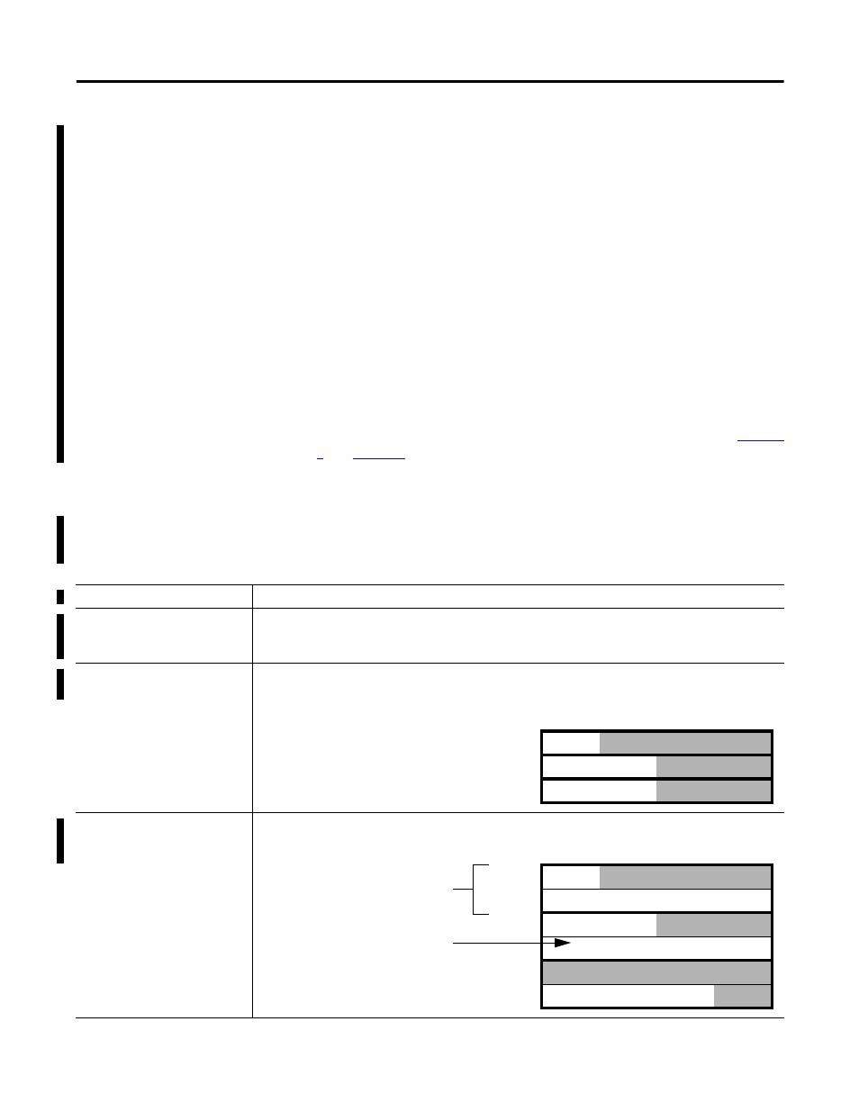
The bytes/node value defines
how much memory for each
address.
AutoScan lets you specify how much input and output memory to give to each address on your network.
DINT
Input Memory
0
device at address 0
1
device at address 1
2
device at address 2
The actual data for the device
fills the portion that it needs
and the rest remains unused.
DINT
Input Memory
0
device at address 0
1
2
device at address 1
3
4
device at address 2
5
The actual data for the
device fills the portion
that it needs and the rest
remains unused.
For example, if you specify 2
DINTs (8 bytes) per address,
the scanner sets aside 2
DINTs for each address.