High speed counter, Function of the frequency counter, Counter frequency and pulse shape – Rockwell Automation 1760-xxxx Pico Controller User Manual User Manual
Page 99: 5 1 f
Publication 1760-UM001D-EN-P - September 2005
Draw a Circuit Diagram with Pico 4-39
Function of the Frequency Counter
High Speed Counter
You can use the high-speed counters to count high frequency signals
reliably.
Pico provides two high-speed up/down counters, C13 and C14, for
use as required. The high-speed counter inputs are permanently
connected to the digital inputs I1 and I2. These counter relays allow
you to count events independently of the cycle time.
The high-speed counters allow you to enter an upper threshold value
as a comparison value. The C13 and C14 high-speed counters are not
dependent on the cycle time.
Counter Frequency and Pulse Shape
The maximum counter frequency is 1 kHz.
The signals must be square waves. We recommend a mark-to-space
ratio of 1:1.
If this is not the case: The minimum mark-to-space ratio is 0.5 ms.
1
2
3
t
g
t
g
t
g
t
g
t
g
t
g
t
g
t
g
4
5
t
g
A
B
C
D
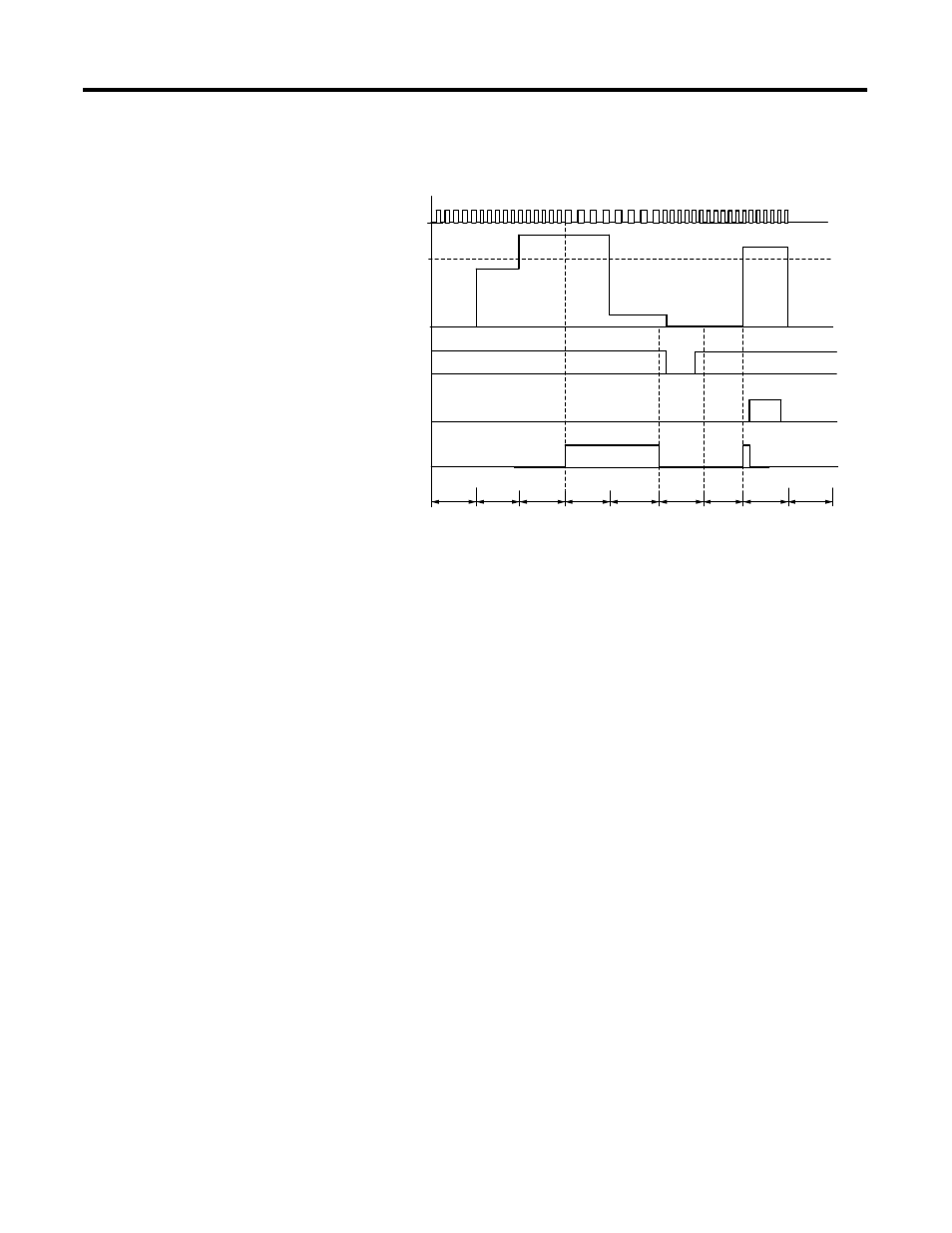
1: Counter input I3 or I4.
2: Upper Setpoint.
3: Enable coil CC...
4: Reset coil RC...
5: Contact (make contact) C... upper setpoint value reached.
tg: Gate time for the frequency measurement.
• Range A: The counter is enabled. Contact C15 (C16)
switches after a frequency above the setpoint was
measured for the first time.
• Range B: If the actual value falls below the setpoint,
the contact is reset. The removal of the enable signal
resets the actual value to zero.
• Range C: The counter is enabled. After a frequency
above the setpoint was measured for the first time,
contact C15 (C16) switches.
• Range D: The reset coil resets the actual value to zero.
t
min
0.5
1
f
max
---------
×
=
t
min
= minimum time of the pulse or pause duration
f
max
= maximum count frequency (1 kHz)