Coil functions – Rockwell Automation 1760-xxxx Pico Controller User Manual User Manual
Page 74
Publication 1760-UM001D-EN-P - September 2005
4-14 Draw a Circuit Diagram with Pico
Coil Functions
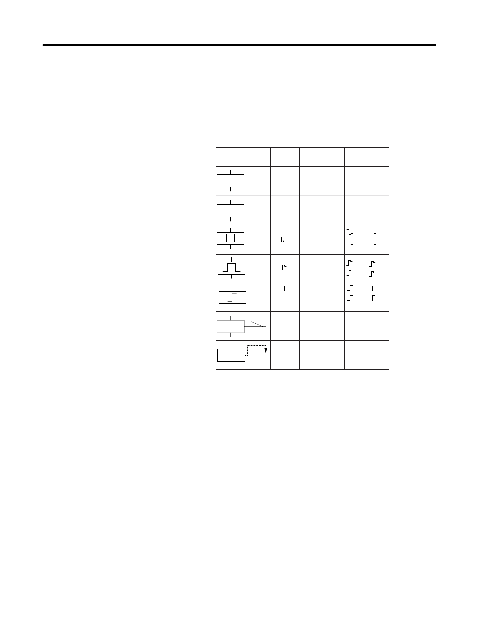
You can set the coil function to determine the switching behavior of
relay coils. The following coil functions are available for relays Q, M,
S, D and ’:’.
The marker relays M and N are used as a flag. The S relay can be used
as the output of an expansion module or, as a marker if no expansion
module is connected. When used as markers, the only difference
between them and the output relay Q is that they have no output
terminals. The functions of timer and counter relays are explained in
the relevant relay description. The coil function { (output energize)
should only be used once on each coil. Otherwise, the last coil in the
circuit diagram determines the status of the relay.
To ensure proper operation of all relay states, only assign the same
coil function once to a relay (S, R).
Exception: The coil function can be used properly several times when
using jumps to structure the circuit diagram.
{
}
S
R
{Q1,{D2,
{S4,{:1,
{M5
}Q1,}D2,
}S4
Q3,
M4,
D8,
S7
Q3,
M4,
D8,
S7
Q3,
M4,
D8,
S7
SQ6,SM2,
SD3,SS4
RQ4,RM5,
RD7,RS3
Output
Energize
Function
Maintained/
Flip-Flop
Function
Set (latching)
Reset
(unlatching)
Coil Function Example
Pico
Symbol
Circuit Diagram
Symbol
Output
Negated
Function
Cycle pulse
falling edge
Cycle pulse
raising edge