Rockwell Automation 1760-xxxx Pico Controller User Manual User Manual
Page 121
Publication 1760-UM001D-EN-P - September 2005
Draw a Circuit Diagram with Pico 4-61
How Does the Shift Register Work?
The shift pulse is switched on for exactly one cycle. To do this, the
shift pulse is generated by evaluating the change from I1 ‘off’ to I1
‘on’ - the rising edge. This allows the shift register to only shift once
regardless of how long I1 remains true.
When I1 is switched on for the first time, marker relay contact M7 is
off and the break contact is closed during the first pass through the
program. Thus, the series circuit consisting of I1, break contact M7
(closed) and M8 is turned on. Although M7 is switched on, this does
not yet affect contact M7.
The contact of M8 (make contact) was still open during the first scan
so a shift pulse is not yet generated. When the relay coil M8 is
activated, Pico transfers the result to the contacts.
In the second scan, break contact M7 opens. The series circuit is now
open. The contact M8 is switched on from the result of the first scan.
Now, all the storage positions are either set or reset in accordance
with the series circuit.
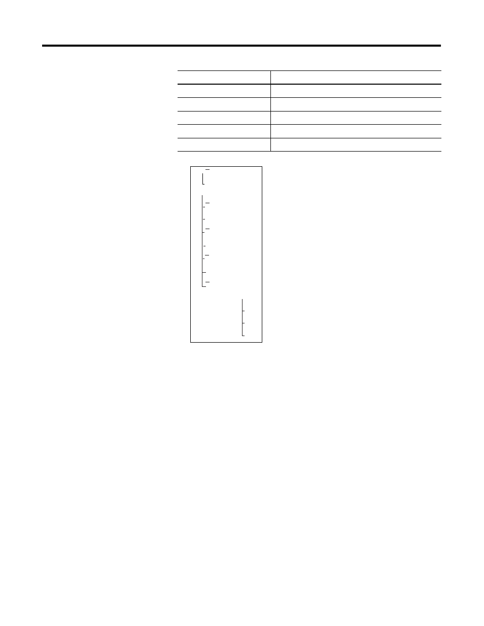
M2
Second storage position
M3
Third storage position
M4
Fourth storage position
M7
Marker relay for one-shot pulse
M8
One-shot pulse used for shift pulse
Item
Function
I1-M7-------{M8
---------{M7
M8-M3-------SM4
M3-------RM4
M2-------SM3
M2-------RM3
M1-------SM2
M1-------RM2
I2-------SM1
I2-------RM1
I3----------RM1
RM2
RM3
RM4
Generate shift pulse
Set 4th storage position
Set 3rd storage position
Set 2nd storage position
Set 1st storage position
Clear 4th storage position
Clear 3rd storage position
Clear 2nd storage position
Clear 1st storage position
Clear all storage position