Protect timer and counter settings, Test circuit using power flow display, Double the flashing frequency – Rockwell Automation 1760-xxxx Pico Controller User Manual User Manual
Page 85
Publication 1760-UM001D-EN-P - September 2005
Draw a Circuit Diagram with Pico 4-25
13. Complete the circuit diagram.
14. Press Ok to store the circuit diagram.
Test Circuit Using Power Flow Display
1. Switch Pico to Run mode and return to the circuit diagram.
Each parameter set can be displayed using the power flow
display for the circuit diagram.
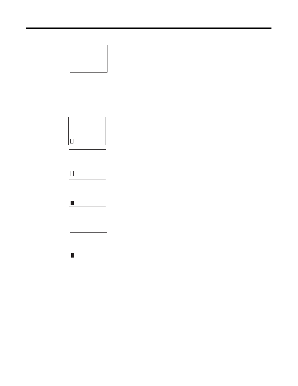
2. Move the cursor onto C1 and press Ok.
The parameter set for the counter is displayed with actual and
setpoint values.
3. Switch I5. The actual value changes.
This is represented in the Pico parameter display. In the last line C:
0007 the counter actual value is equal to seven.
If the actual value is greater than or equal to the setpoint (10), the left
character on the bottom row changes to a black box. The contact of
counter C1 switches.
The counter contact triggers the timing relay. This causes the warning
light to flash at output Q1.
Double the flashing frequency:
1. Select T1 in the power flow display and press Ok.
2. Change the set time I1 to 00.500 and I2 to 00.250
(0.5 and 0.25 s).
3. Press Ok to save the set time.
The character on the left of the bottom row indicates whether the
contact has switched or not.
Protect Timer and Counter Settings
You can also modify parameter settings via the PARAMETER menu
option. If you want to prevent other people from modifying the
parameters, change the access enable symbol from ’+’ to ’-’ when
creating the circuit diagram and protect the circuit diagram with a
password.
I5----------CC1
I6----------RC1
C1----------TT1
T1----------{Q1
C1 N +
C: 0000
0010
S
C1 N +
C: 0007
0010
S
C1 N +
C: 0010
0010
S
T1
Ü S +
00.500
S1
00.250
00.200
S2
T: