Relays – Rockwell Automation 1760-xxxx Pico Controller User Manual User Manual
Page 65
Publication 1760-UM001D-EN-P - September 2005
Draw a Circuit Diagram with Pico 4-5
Relays
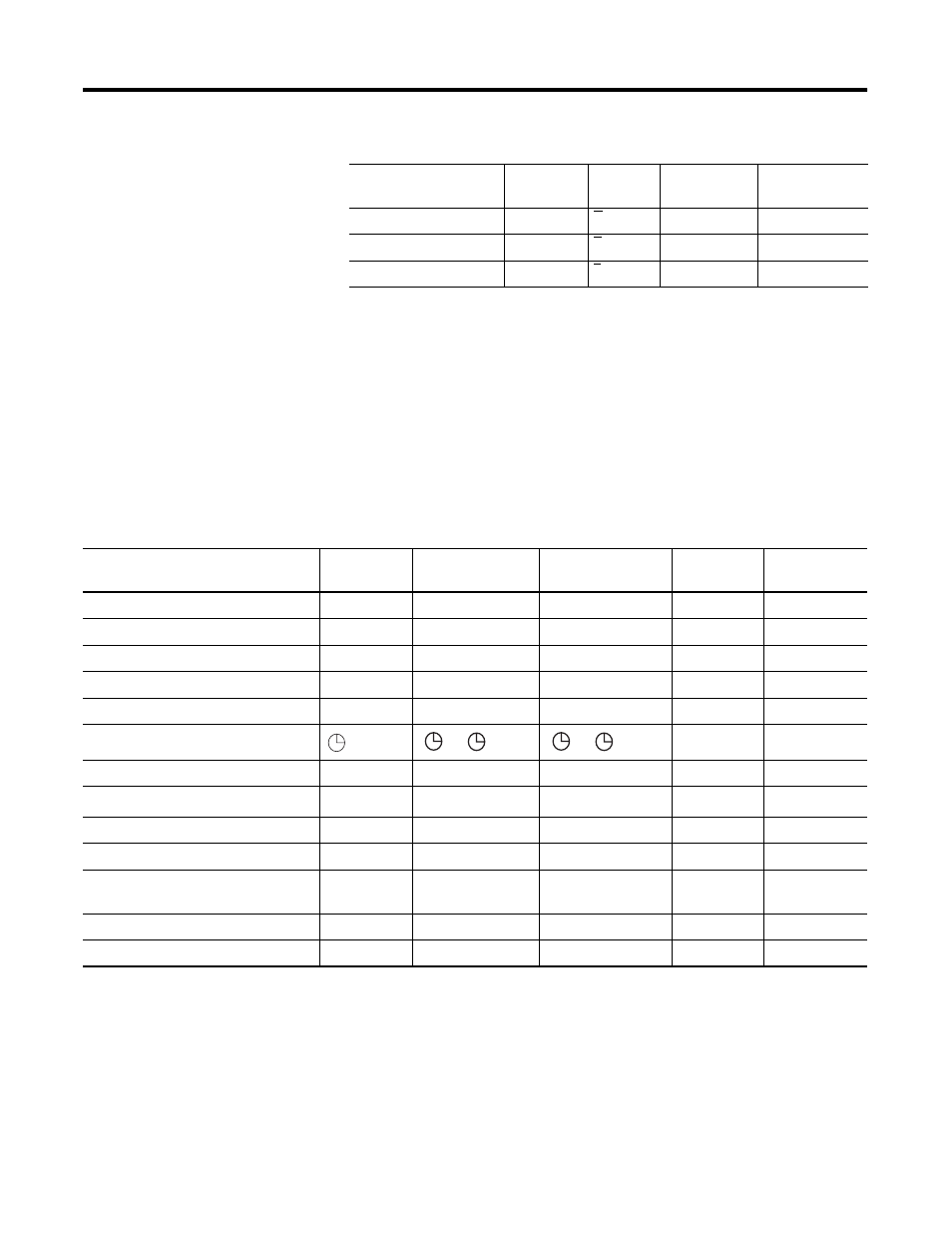
Pico has nine different types of relay for use in a circuit diagram.
Operating Hours Counter
O
O
O1 to O4
O1 to O4
Year Time Switch
Y
Y
Y1 to Y8
Y1 to Y8
Master Reset
Z
Z
Z1 to Z3
Z1 to Z3
(1) Not available on “-NC” models.
(2) This applies only to the 1760-LxxBWB-xx and 1760-L12DWD.
(3) This applies only to 1760-L18xxx-EX models. R15 and R16 are used for expansion overload detection for the
transistor expansion module, 1760-IB12XOB8, as described on page 9-4.
Contact Type
Make
Contact
Break
Contact
1760-L12xxx
1760-L18xxx
1760-L20xxx
Relay type
Pico Symbol 1760-L12xxx
1760-L18xxx
1760-L20xxx
Coil
Function
Parameter
Controller Outputs
Q
Q1 to Q8
Q1 to Q8
X
–
Internal Marker Bits
M
M1 to M16
M1 to M16
X
–
Internal Marker Bits
N
N1 to N16
N1 to N16
X
–
Counters
C
C1 to C16
C1 to C16
X
X
Timers
T
T1 to T16
T1 to T16
X
X
Real Time Clock
(1)
–
X
Operating Hours Counters
O
O1 to O4
O1 to O4
X
X
Analog Setpoint Compare
(2)
A
A1 to A16
A1 to A16
–
X
Text Display
D
D1 to D16
D1 to D16
X
X
Jump to Label
:
:1 to :8
:1 to :8
X
–
Expansion Outputs or Internal Marker
Bits
S
S1 to S8 (as marker) S1 to S8
X
–
Year Time Switch
Y
Y1 to Y8
Y1 to Y8
–
X
Master Reset
Z
Z1 to Z3
Z1 to Z3
X
–
(1) Not available on “-NC” models.
(2) This applies only to the 1760-LxxBWB-xx and 1760-L12DWD.
1 to
8
1 to
8