Test the circuit diagram, Power flow display – Rockwell Automation 1760-xxxx Pico Controller User Manual User Manual
Page 58
Publication 1760-UM001D-EN-P - September 2005
3-8 Commission the Pico
Test the Circuit Diagram
1. Switch to the main menu and select the RUN menu option
(press Esc to go back to the Main Menu and use the arrow keys
to highlight RUN).
2. Toggle between RUN and STOP to set the operating mode
required (use the Ok button to toggle between RUN and STOP).
Pico is in Run mode if the STOP menu option is displayed.
Menu options that toggle between two functions always show
the next possible setting.
The status display shows the current mode and the switching
states of the inputs and outputs.
3. Change to the Status display by pressing Esc and actuate
push-button S1.
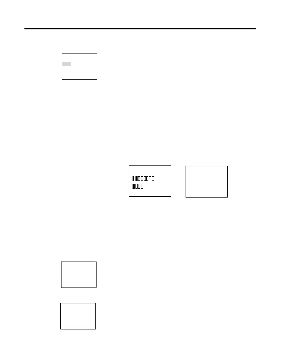
The boxes for inputs I1 and I2 are activated and relay Q1 is energized.
Power Flow Display
Pico allows you to check programs in Run mode. This means that you
can check your circuit diagram via the built-in power flow display
while it is being processed by Pico.
1. Press Ok twice to change to the Circuit diagram display and
actuate push-button S1.
The relay energizes and Pico shows the flow of current.
2. Press push-button S2, that has been connected as a break
contact.
The circuit connection is interrupted and relay Q1 drops out.
PROGRAM...
STOP
å RUN
PARAMETER
INFO...
I12345678
MO
12:50
Q1234
RUN
12..........
MO
02:00
1..........RUN
Pico 1760-L12xxx
Pico 1760-L18xxx
I1-I2-------{Q1
I1-I2-------{Q1