Creating a ladder logic program 5-7 – Rockwell Automation 1203-GK5 DeviceNet Communications Module FRN 1.xxx-3.xxx User Manual
Page 67
Creating a Ladder Logic Program
5-7
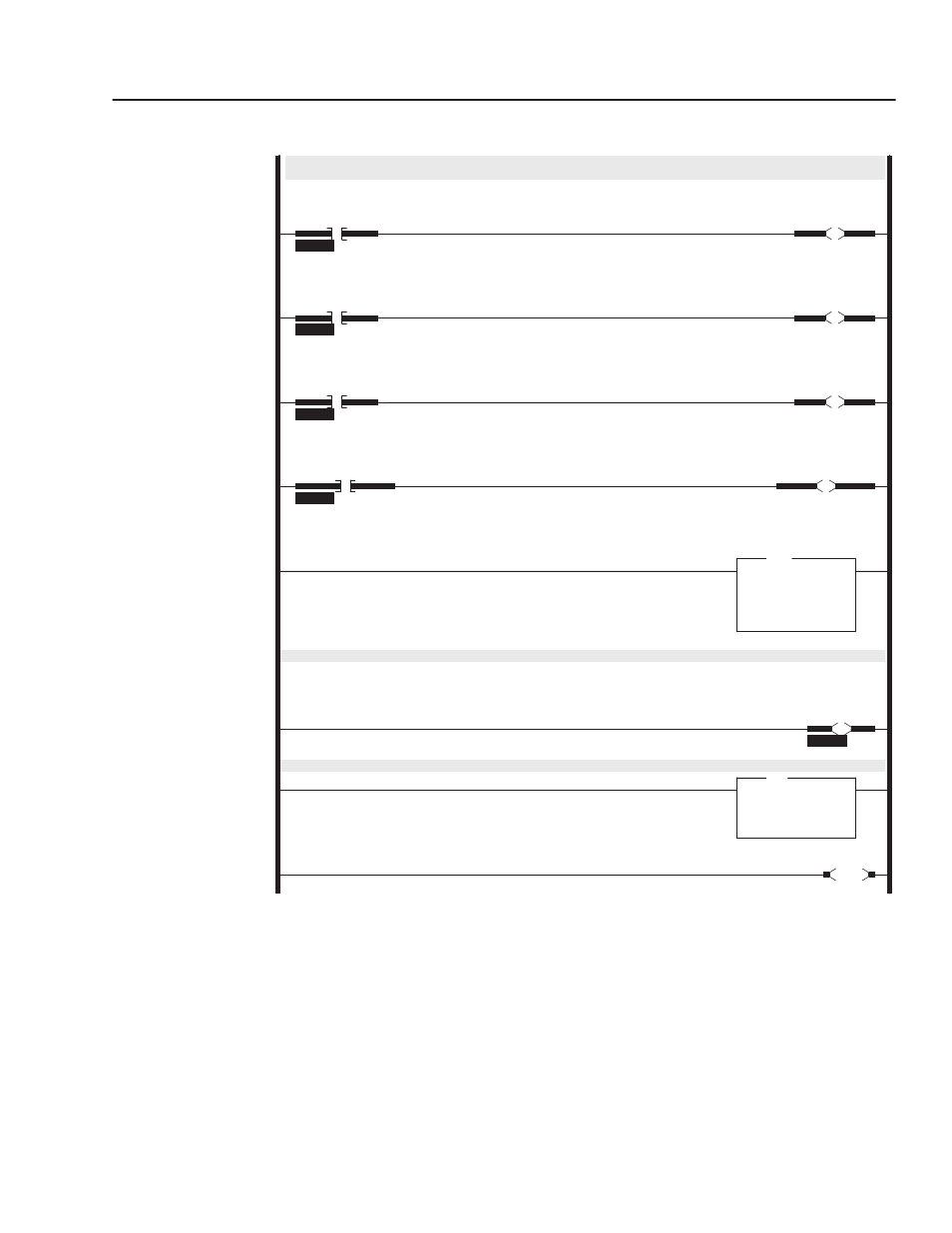
Figure 5.3
Example SLC Ladder Logic Program (Continued)
0008
MOV
Move
Source
N21:0
0<
Dest
N10:1
0<
MOV
1336PLUS
REFERENCE
Command Word
This rung enables the scanner. (Changes the scanner into RUN mode)
0009
O:1.0
0
1747-SDN
1747-SDN
Scanner
Enable
Bit
This rung copies the drive command data to the scanner and out to the drive via DeviceNet.
0010
COP
Copy File
Source
#N10:0
Dest
#M0:1.0
Length
128
COP
0011
END
Rungs 0004 through 0008 move the operator’s inputs from the operator station to the N9 data file where they will be sent to the scanner
and out to the drive via DeviceNet.
0004
I:2.0
0
1746-I*16
Operator Input
Drive Start
Command Bit
N10:0
1
1336PLUS
START
Command Bit
0005
I:2.0
1
1746-I*16
Operator Input
Drive Stop
Command Bit
N10:0
0
1336PLUS
STOP
Command Bit
0006
I:2.0
2
1746-I*16
Operator Input
Drive Jog
Command Bit
N10:0
2
1336PLUS
JOG
Command Bit
0007
I:2.0
3
1746-I*16
Operator Input
Drive Clear Faults
Command Bit
N10:0
3
1336PLUS
CLEAR FAULTS
Command Bit