Rockwell Automation 1203-GK5 DeviceNet Communications Module FRN 1.xxx-3.xxx User Manual
Page 32
3-4
Installing the 1203-GK5 Module or 1336-GM5 Board
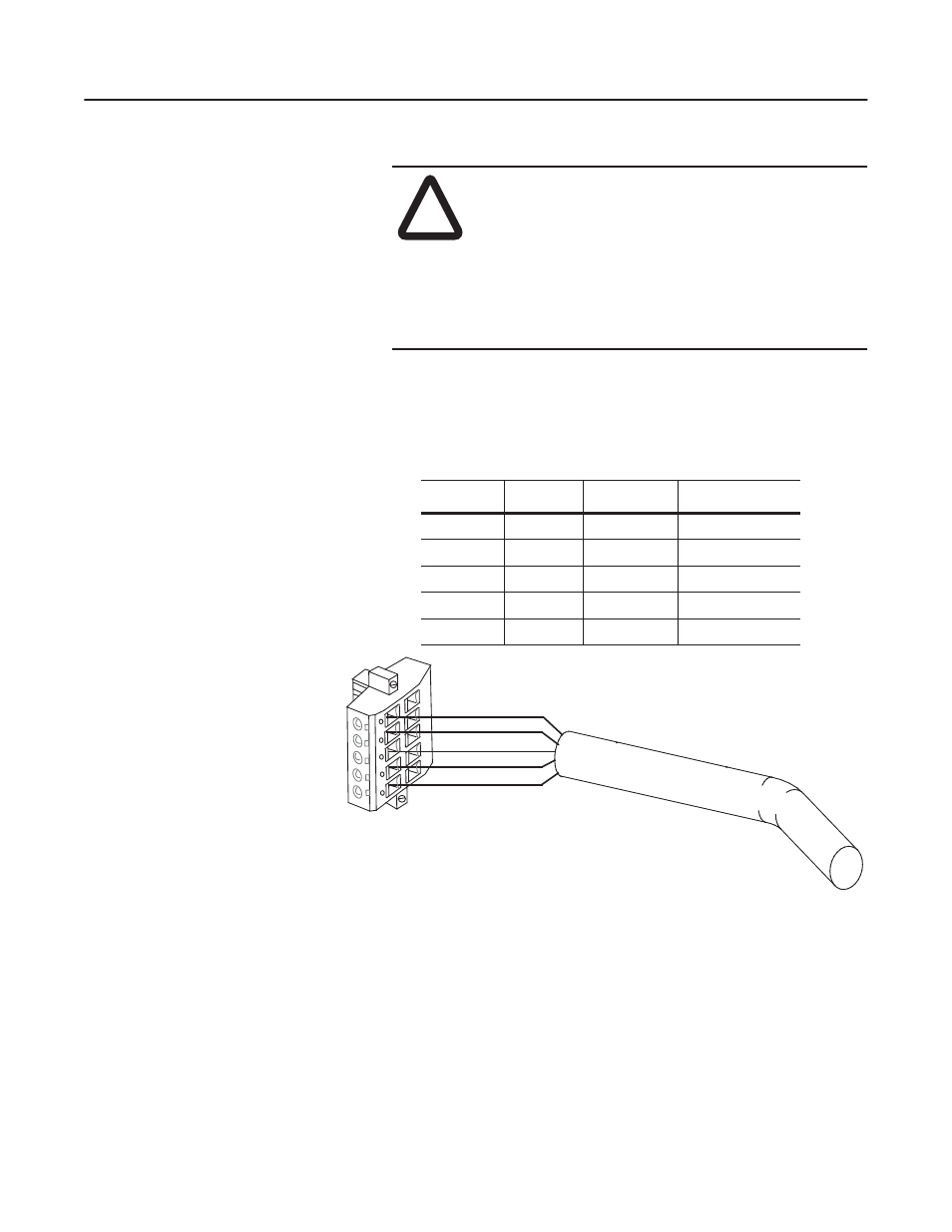
3. Insert the DeviceNet cable wires into the 5-pin or 10-pin
connector.
Figure 3.3
Inserting DeviceNet Cable Wires into a 10-Pin Connector
!
ATTENTION: If you wire the 5-pin or 10-pin header
after you have connected it to the module, static control
precautions are required. Device malfunction may occur
if you do not follow ESD control procedures. If you are
not familiar with static control procedures, refer to
Rockwell Automation Publication 8000-4.5.2,
Guarding Against Electrostatic Damage, or other
applicable ESD protection handbook.
The Communication Module receives power and communications through the DeviceNet connector.
DeviceNet cable wires connect to the DeviceNet plug terminal block as shown in the following table.
Color
Terminal
Signal
Function
Black
1
COM
Common
Blue
2
CAN_L
Signal Low
Bare
3
SHIELD
Shield
White
4
CAN_H
Signal High
Red
5
PWR
Power Supply
Red
White
Bare
Blue
Black
5
4
3
2
1