Rockwell Automation 1203-GK5 DeviceNet Communications Module FRN 1.xxx-3.xxx User Manual
Page 17
Overview
1-5
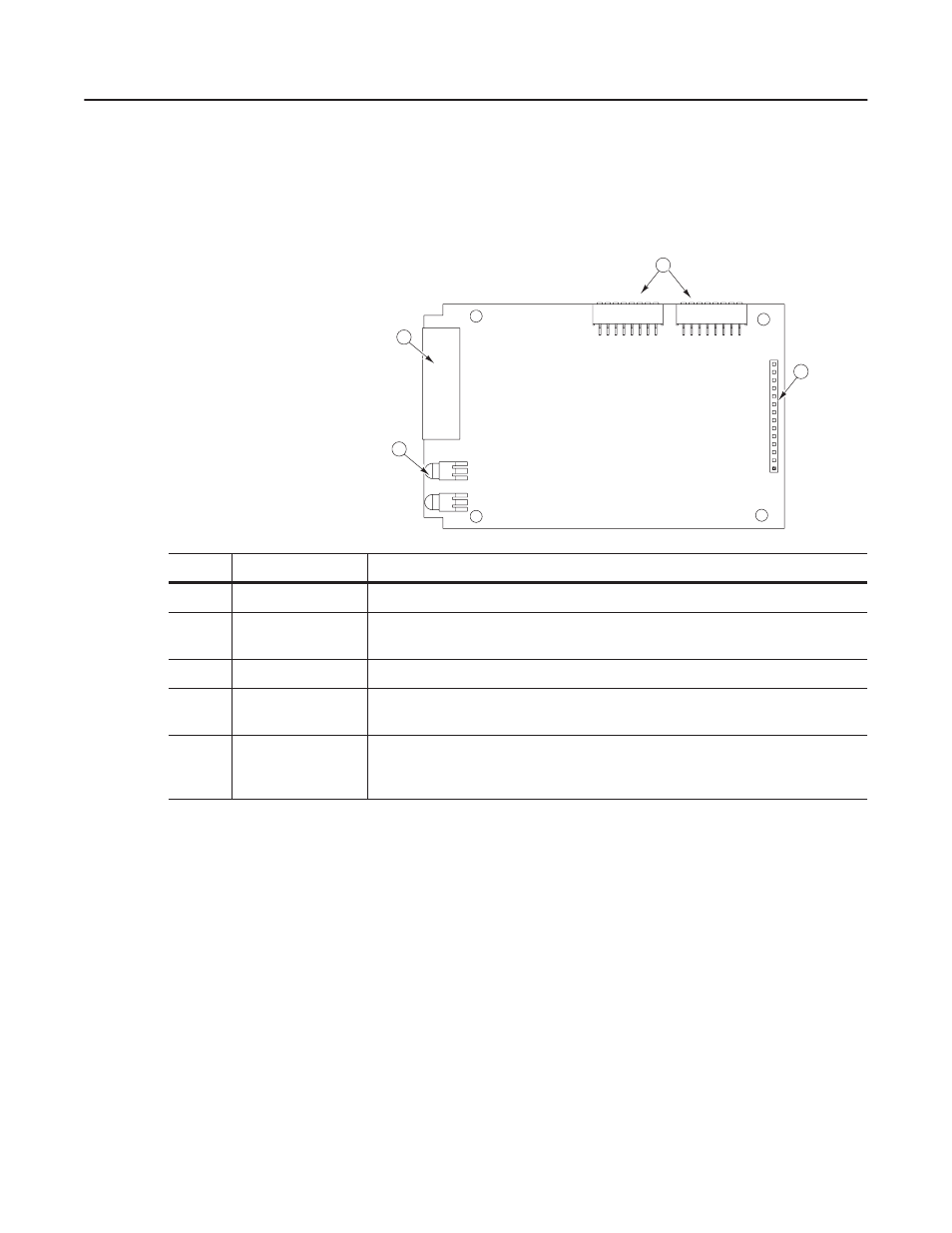
1336-GM5 Board Hardware
Figure 1.4 illustrates and the following table lists the main parts of the
1336-GM5 DeviceNet communications board:
Figure 1.4
Parts of the 1336-GM5 Board
Overview of Setting Up the
1203-GK5 Module or 1336-GM5
Board
To set up the 1203-GK5 module or 1336-GM5 board, you must
perform the following tasks:
1. Set the node address and configure the parameters. Refer to
Chapter 2, Configuring the 1203-GK5 Module or 1336-GM5
Board.
2. Install the module or mount the board. Refer to Chapter 3,
Installing the 1203-GK5 Module or 1336-GM5 Board.
3. Configure a scanner (either PLC or SLC) to communicate with
the new node. Refer to Chapter 4, Configuring a Scanner to
Communicate with the 1203-GK5 Module or 1336-GM5 Board.
4. If necessary, create a ladder logic program to control the
SCANport product. Refer to Chapter 5, Creating a Ladder Logic
Program.
1
2
3
AB0936
4
Number
Part
Description
1
DeviceNet Connection
Provides a 5-pin Phoenix connector to attach the module to the DeviceNet network.
2
Bi-Color LEDs
Indicate the status of the DeviceNet media channel and of the SCANport connection. For more
information, refer to Chapter 7, Troubleshooting.
3
SCANport Connection
Provides a 14-pin connector containing power and SCANport communication circuitry.
4
DIP Switches
Located on the bottom of the module, these switches are used to configure the module. For
more information, refer to Chapter 2, Configuring the 1203-GK5 Module or 1336-GM5 Board.
Not
Shown
Kit
Provides the necessary materials for mounting the board to the SCANport product. These
materials include one grounding wrist strap, four Phillips mounting screws, four stand-off nylon
headers, one 5-pin connector, and one snap-in comm housing with mounting instructions.