Rockwell Automation 1203-GK5 DeviceNet Communications Module FRN 1.xxx-3.xxx User Manual
Page 63
Creating a Ladder Logic Program
5-3
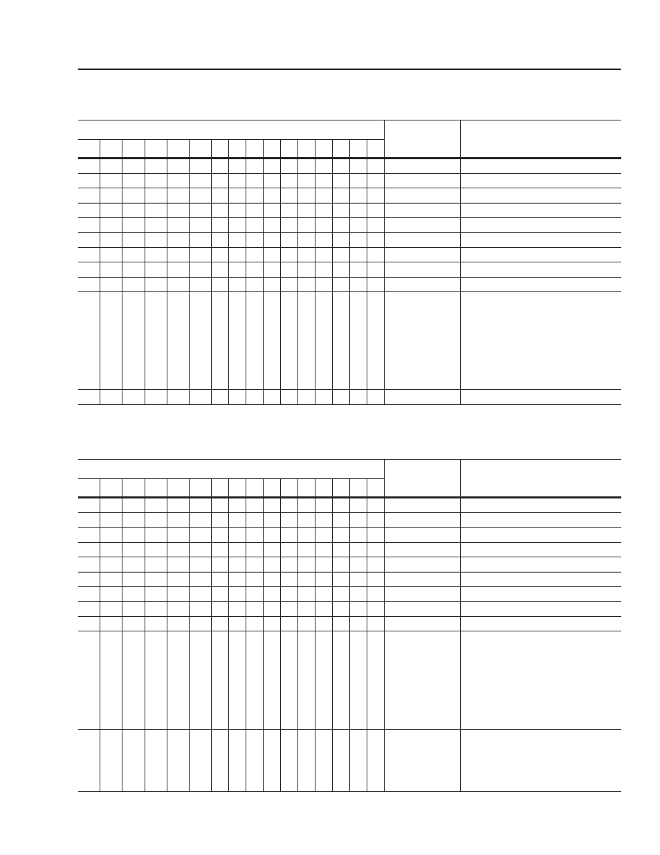
The 1305, 1336 PLUS, or 1336 PLUS II drive in this example accepts
the following Logic Command Data from the controller.
The 1305, 1336 PLUS, or 1336 PLUS II drive in this example sends
the following Logic Status Data to the PLC.
Logic Command Bits
Function
Description
15
14
13
12
11
10
9
8
7
6
5
4
3
2
1
0
X Stop
1=Stop, 0=No Operation
X
Start
1=Start, 0=No Operation
X
Jog
1=Jog, 0=No Operation
X
Clear Faults
1=Clear, 0=No Operation
X
X
Direction
00=No Operation, 01=Forward, 10=Reverse
X
Local
1=Local, 0=Multiplexed
X
MOP Increment
1=Increment MOP, 0=No Operation
X
X
Accel Rate Select
00=No Operation, 01=Rate 1, 10=Rate 2
X
X
Decel Rate Select
00=No Operation, 01=Rate 1, 10=Rate 2
X
X
X
Reference
Selection
000=No Operation
001=External Reference 1 (Par 5)
010=External Reference 2 (Par 6)
011=Preset 3
100=Preset 4
101=Preset 5
110=Preset 6
111=Preset 7
X
MOP Decrement
1=Decrement MOP, 0=No Operation
Logic Status Bits
Function
Description
15
14
13
12
11
10
9
8
7
6
5
4
3
2
1
0
X Enabled
1=Enabled, 0=Not Enabled
X
Running
1=Running, 0=Not Running
X
Command Direction 1=Forward, 0=Reverse
X
Rotating Direction
1=Forward, 0=Reverse
X
Acceleration
1=Accelerating, 0=Not
X
Deceleration
1=Decelerating, 0=Not
X
Warning
1=Warning Present, 0=Not
X
Fault
1=Faulted, 0=Not Faulted
X
At Speed
1=At Speed, 0=Not At Speed
X
X
X
Local
000=Terminal I/O has Local
001=Port 1 has Local
010=Port 2 has Local
011=Port 3 has Local
100=Port 4 has Local
101=Port 5 has Local
110=Port 6 has Local
111=Multiplexed Control
X
X
X
X
Reference Source
0000=External Reference 1
0001 – 0111=Presets 1 – 7
1000=External Reference 2
1001 – 1110=Port 1 – 6 Direction
1111=Jog