Hardware and parts description – Rockwell Automation 1203-GK5 DeviceNet Communications Module FRN 1.xxx-3.xxx User Manual
Page 16
1-4
Overview
Hardware and Parts Description
The hardware included with the adapter depends on the adapter that
you have.
1203-GK5 Module Hardware
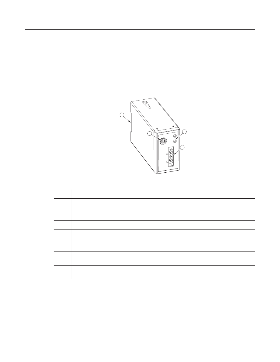
Figure 1.3 illustrates and the following table lists the main parts of the
1203-GK5 DeviceNet communications module:
Figure 1.3
Parts of the 1203-GK5 Module
4
3
1
2
AB0935
Number
Part
Description
1
DeviceNet Connection
Provides a 5-pin Phoenix connector to attach the module to the network.
2
Bi-Color LEDs
Indicate the status of the DeviceNet media channel and of the SCANport connection. For
more information, refer to Chapter 7, Troubleshooting.
3
SCANport Connection
Provides a standard SCANport 8-pin circular mini-DIN connector for the SCANport cable.
4
DIN Rail Mount
Securely attaches and electronically grounds the module to the DIN rail.
Not
Shown
DIP Switches
Located on the bottom of the module, these switches are used to configure the module. For
more information, refer to Chapter 2, Configuring the 1203-GK5 Module or 1336-GM5 Board.
Not
Shown
5-Pin Plug-In
Connector
This part is supplied with the module. The 5-pin plug-in connector is a connector to attach to
the DeviceNet cable.
Not
Shown
10-Pin Plug-In
Connector
This part is supplied with the module. The 10-pin plug-in connector is a connector to attach to
the DeviceNet cable.