Standard cable pinouts, Table – Wasp Barcode WLS9600 Product Reference Guide User Manual
Page 271
Technical Specifications
Product Reference Guide
261
Standard Cable Pinouts
provide standard pinout information.
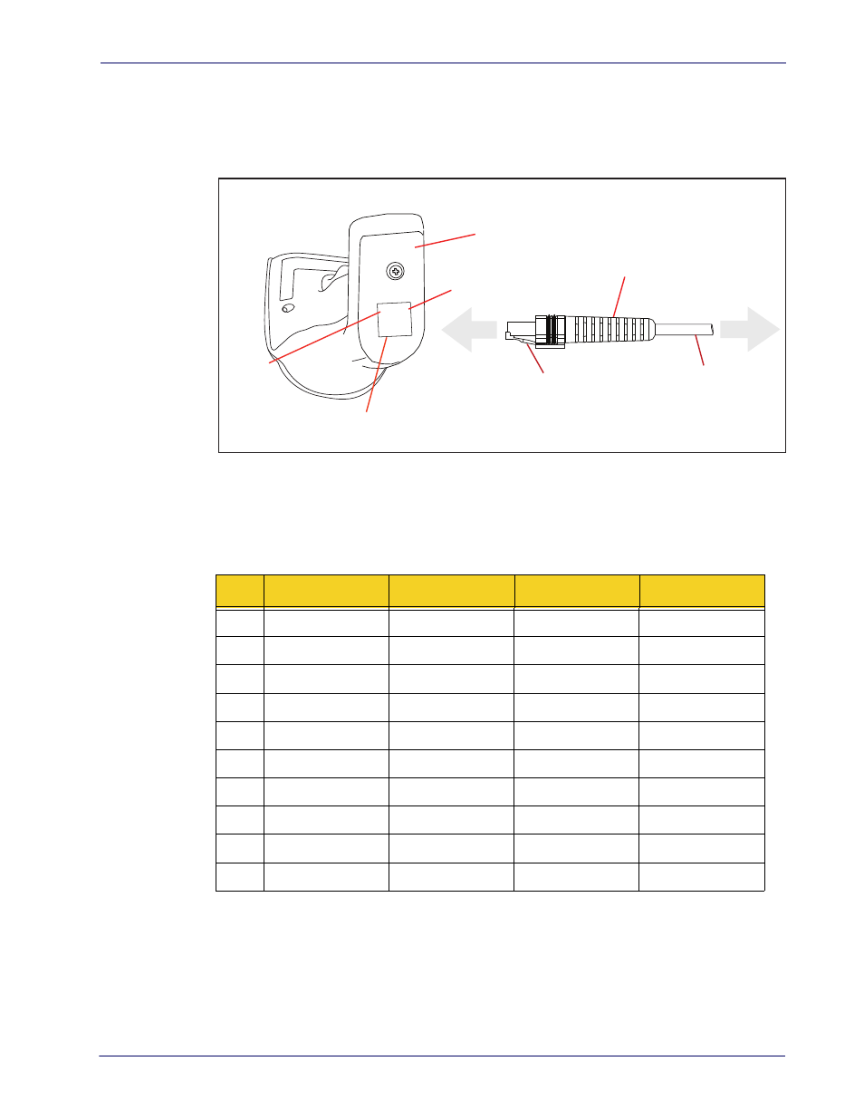
Figure 10. Standard Cable Pinouts
Pin 10
Cable Clip (Latch)
To Host
Cable
Cable Strain Relief
Bottom of Scanner
Interface Cable Port
Pin 1
The signal descriptions in Table
apply to the connector on the reader and are for reference
only.
Table 46.
Standard Cable Pinouts — Reader Side
Pin
RS-232
OEM
USB
Keyboard Wedge
1
RTS (out)
2
D+
CLKIN (KBD side)
3
D-
DATAIN (KBD side)
4
GND
GND
GND
GND
5
RX
6
TX
7
VCC
VCC
VCC
VCC
8
IBM_B
CLKOUT (PC side)
9
IBM_A
DATAOUT (PC side)
10
CTS (in)