Network interface – TCI HGA Manual User Manual
Page 96
96
Network Interface
The network interface on the Interface Module allows basic Run/Stop commands and internal status data and
can be communicated to and from the HarmonicGuard Active filter. The HMI display implements an
integrated ModbusRTU slave device for the network interface (see the HMI Display Connection section) or
an optional network communications gateway can be used such as Ethernet/IP to implement other protocols
(see Appendix).
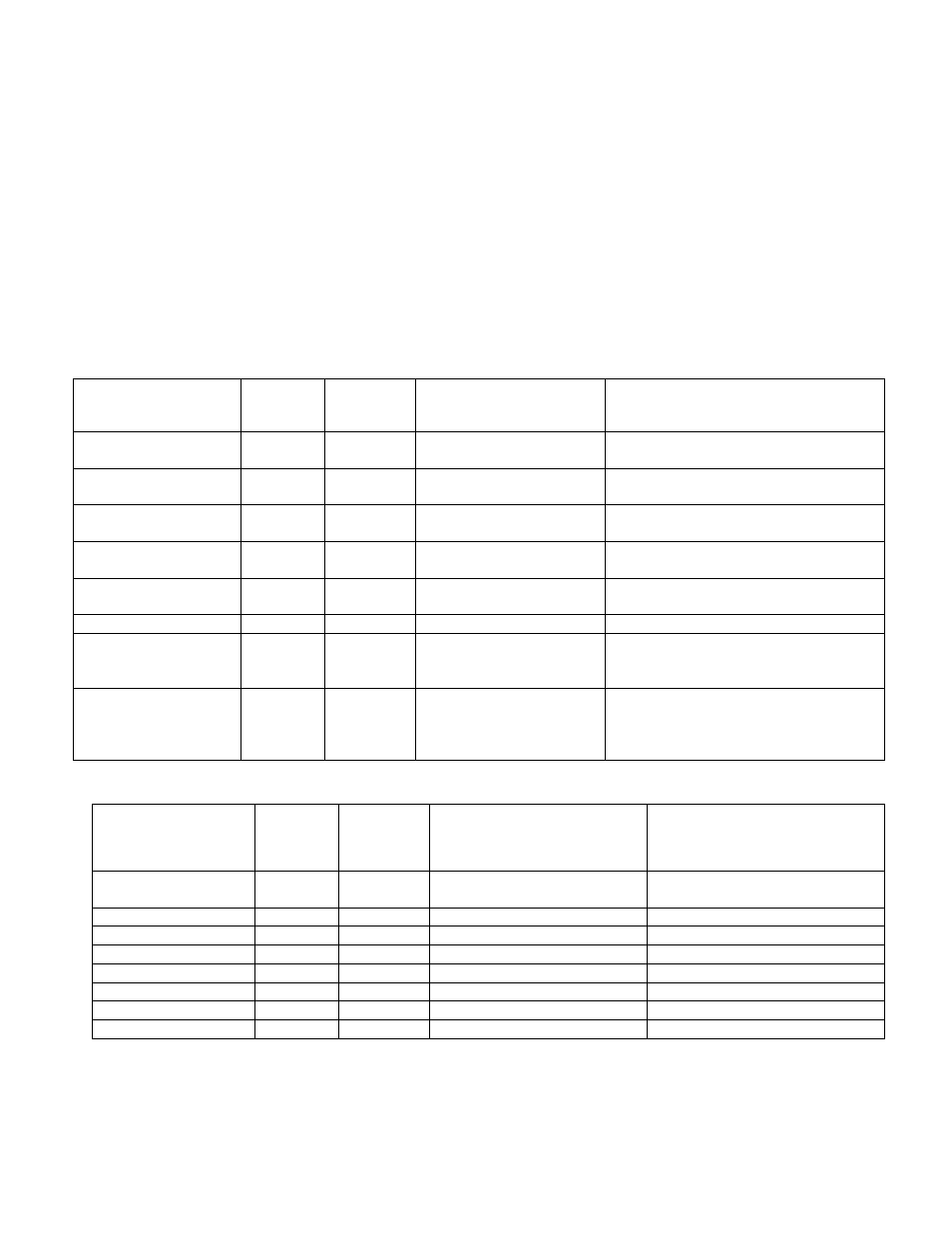
The input/output register maps of the data available from the network interface are available in Table 7.18
and Table 7.19. All input and output registers are two bytes in size. For the base address of the input and
output data sections please reference the connection sections in this manual specific to the configured
protocol. For the integrated ModbusRTU network interface reference the HMI Display Connection section. If
an option Communications Gateway is configured reference the appendix.
Table 7.19 – Network Interface OUTPUT Register Map
Parameter Name
I/O Reg
Address
Offset
Direction
Format
Description
SYS_RUNNING
0
Output
0 = Running
1 = Idle
Indicates if the HGA filter is currently
running or in the idle state
SYS_POWER_ON
1
Output
0 = Power Off
1 = Power On
Indicates if the HGA filter has input
power available
SYS_FAULTED
2
Output
0 = Not faulted
1 = Faulted
Indicates if the HGA filter is faulted
SYS_IN_I_LIMIT
3
Output
0 = Nominal
1 = At Capacity
Indicates if the HGA filter is running at
its maximum capacity
V_LINE_LL_RMS
4
Output
Volts RMS
Source Utility Line Phase to Phase
Voltage
I_LINE_RMS
5
Output
Amps RMS
Line/Load Phase Current
I_LINE_PF
6
Output
1000 = 1.0 Unity PF
-950 = 0.95 Lagging PF
950 = Leading PF
Line/Load Power Factor - Negative
values indicate lagging power factor
SYS_NW_START_E
N
7
Output
0 = Network Run
Disabled
1 = Network Run
Enabled
Network Run/Stop command enable
setpoint
Table 7.20 – Network Interface INPUT Register Map
Parameter Name
I/O Reg
Address
Offset
Direction
Format
Description
SYS_NW_START_I
N
0
Input
0 = Network Command Stop
1 = Network Command Run
Remote Network Run/Stop
command to the HGA
unused
1
Input
-
-
unused
2
Input
-
-
unused
3
Input
-
-
unused
4
Input
-
-
unused
5
Input
-
-
unused
6
Input
-
-
unused
7
Input
-
-
The network Run/Stop command allows a remote network to send a run command to the HarmonicGuard
Active filter. The network command input will only be acknowledged if the Relay Run/Stop Enable is set to
ENABLED on the HMI Display setup screen. Pressing stop locally via the HMI Display will set the enable
for the Relay Run/Stop Enable to DISABLED.